Combustor and gas turbine having the same
a gas turbine and combustor technology, applied in the direction of instruments, heat measurement, lighting and heating apparatus, etc., can solve the problems of gas turbine combustion oscillations, space limitations in the casing during installation, etc., to reduce the space needed outside the combustor, reduce manufacturing costs, and facilitate extraction
- Summary
- Abstract
- Description
- Claims
- Application Information
AI Technical Summary
Benefits of technology
Problems solved by technology
Method used
Image
Examples
first embodiment
[0049]Referring to FIGS. 1 to 4, a gas turbine 1 according to a first embodiment of the present invention will be described.
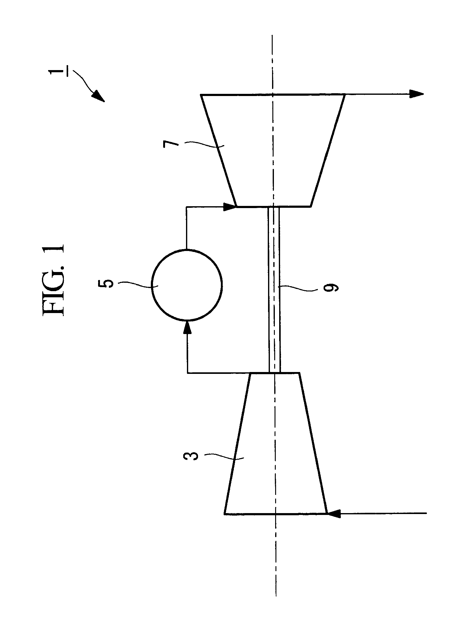
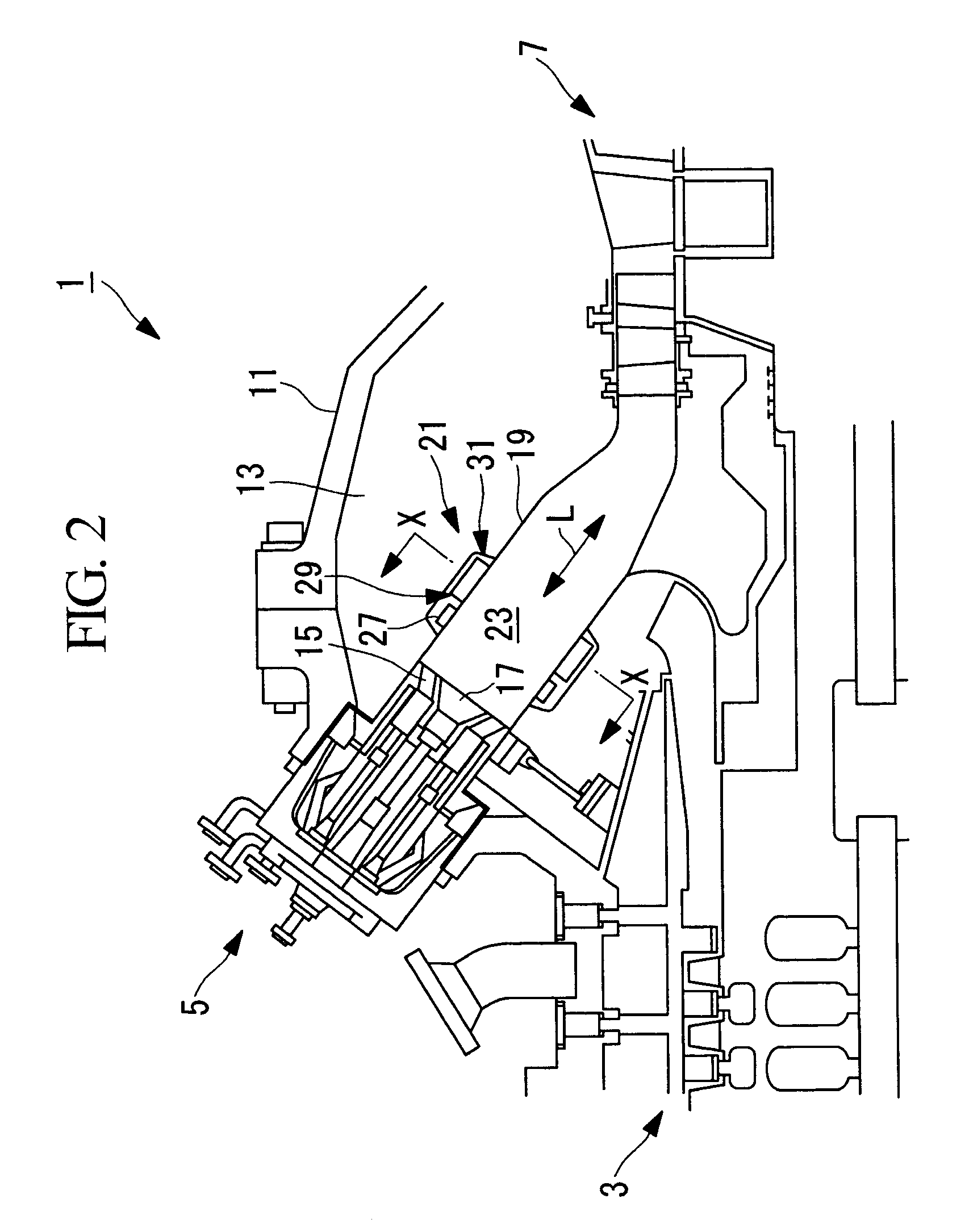
[0050]FIG. 1 is a schematic view for describing the configuration of the gas turbine 1 according to this embodiment. FIG. 2 is a schematic view for describing, in outline, the configuration of combustors 5 in FIG. 1.
[0051]As shown in FIGS. 1 and 2, the gas turbine 1 includes a compressor 3, the combustors 5, a turbine unit (turbine) 7, a rotation shaft 9, and a housing 11 that accommodates these components in place.
[0052]The compressor 3 takes in and compresses the atmosphere, which is the outside air, and supplies the compressed air to the combustors 5.
[0053]Note that the configuration of the compressor 3 may be any known one and is not specifically limited.
[0054]As shown in FIG. 1, the combustors 5 generate combustion gas (high-temperature gas) by mixing the air compressed by the compressor 3 and externally supplied fuel and combusting the mixed gaseous mixtu...
second embodiment
[0113]Next, a second embodiment of the present invention will be described with reference to FIGS. 6 and 7.
[0114]Although the basic configuration of the gas turbine according to this embodiment is the same as that according to the first embodiment, the configuration of the attenuating device 21 is different from that according to the first embodiment. Accordingly, in this embodiment, the attenuating device 21, which is different from that according to the first embodiment, will be mainly described, and overlapping descriptions of the other components will be omitted.
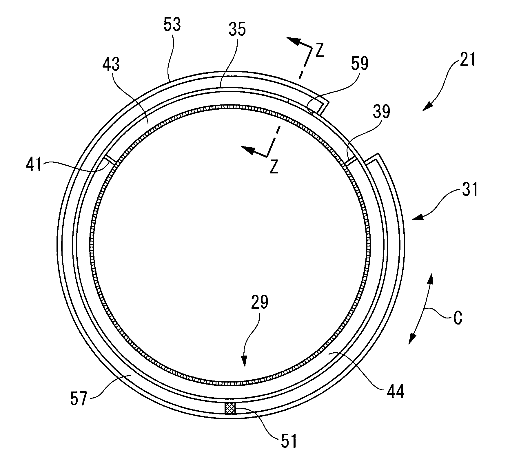
[0115]FIG. 6 is a cross-sectional view for describing the configuration of the relevant part of the attenuating device 21 in the combustor 5 of the gas turbine 1 according to this embodiment. FIG. 7 is a cross-sectional view taken along line Z-Z in FIG. 6.
[0116]Note that the components the same as those in the first embodiment will be denoted by the same reference numerals, and the descriptions thereof will be omitted.
[0...
third embodiment
[0132]Next, a third embodiment of the present invention will be described with reference to FIGS. 8 and 9. Although the basic configuration of the gas turbine according to this embodiment is the same as that according to the first embodiment, the configuration of the attenuating device 21 is different from that according to the first embodiment. Accordingly, in this embodiment, the attenuating device 21, which is different from that according to the first embodiment, will be mainly described, and overlapping descriptions of the other components will be omitted.
[0133]FIG. 8 is a cross-sectional view for describing the configuration of the relevant part of the attenuating device 21 in the combustor 5 of the gas turbine 1 according to this embodiment. FIG. 9 is a cross-sectional view taken along line W-W in FIG. 8. Note that the components the same as those in the first embodiment will be denoted by the same reference numerals, and the descriptions thereof will be omitted.
[0134]The aco...
PUM
 Abstract
Description
Claims
Application Information
 - R&D
- Intellectual Property
- Life Sciences
- Materials
- Tech Scout
- Unparalleled Data Quality
- Higher Quality Content
- 60% Fewer Hallucinations
Browse by: Latest US Patents, China's latest patents, Technical Efficacy Thesaurus, Application Domain, Technology Topic, Popular Technical Reports.
© 2025 PatSnap. All rights reserved.Legal|Privacy policy|Modern Slavery Act Transparency Statement|Sitemap|About US| Contact US: help@patsnap.com


