Interferometer employing a multi-waveguide optical loop path and fiber optic rotation rate sensor employing same

a multi-waveguide optical loop and interferometer technology, applied in the field of sagnac interferometer, can solve the problems of increasing the difficulty of winding accurately, the physical length of multi-waveguide fiber, and the inability to achieve perfect reduction, so as to increase the sagnac phase difference in fog, reduce the physical length of multi-waveguide fiber, and reduce the fiber length of the fiber coil

Active Publication Date: 2013-07-30
BERGH RALPH A
View PDF9 Cites 8 Cited by
  • Summary
  • Abstract
  • Description
  • Claims
  • Application Information

AI Technical Summary

Benefits of technology

[0022]In accordance with the embodiments as just described, the innovative FOG architecture employing the novel optical fiber coil construction of multiple waveguides will increase the Sagnac phase difference in a FOG while reducing the physical length of the multi-waveguide fiber in the fiber coil. Reducing the fiber length of the fiber coil results in a smaller size coil and improved thermal performance characteristics. Further, using multiple fiber cores or waveguides or bundle of waveguides increases the Sagnac phase difference for a given length of fiber by a factor equal to the number of cores or waveguides.

Problems solved by technology

Reducing the fiber diameter increases the length of fiber that will fit into the space allotted, but the fiber becomes more delicate and increasingly difficult to wind accurately as the size is reduced.
The reason is that the clockwise and counter-clockwise waves traverse almost identical paths so that common-mode errors tend to cancel each other.
This reduction is not perfect because the two waves traverse a given section of fiber at different times.
The FOG has been very successful in a limited number of applications.
The increased fiber length only works in benign conditions or when the temperature is controlled because errors due to environmental perturbations scale with length.
If the FOG is designed and constructed well, its ability to accurately measure rotation rate is limited by the stability of the present state-of-the-art fiber coil as it is subjected to a changing environment.
Increasing the diameter of the coil has the obvious problem of increasing the size of the FOG.
Increasing the number of turns of fiber also increases the size of the coil, and it reduces the coil stability.
This causes a time-varying strain gradient if the temperature is varying in time, and thereby causes a measurement error.
In some cases the error can be measured and compensated for to some extent; in other cases it is not easy to distinguish the error from rotation-rate measurement, and it is not possible to compensate for the error.
The quest for ever larger signal can result in very large diameter FOGs that become challenging to package and to stabilize in a dynamic environment.

Method used


Image

  • Interferometer employing a multi-waveguide optical loop path and fiber optic rotation rate sensor employing same
  • Interferometer employing a multi-waveguide optical loop path and fiber optic rotation rate sensor employing same
  • Interferometer employing a multi-waveguide optical loop path and fiber optic rotation rate sensor employing same

Examples


Embodiment Construction

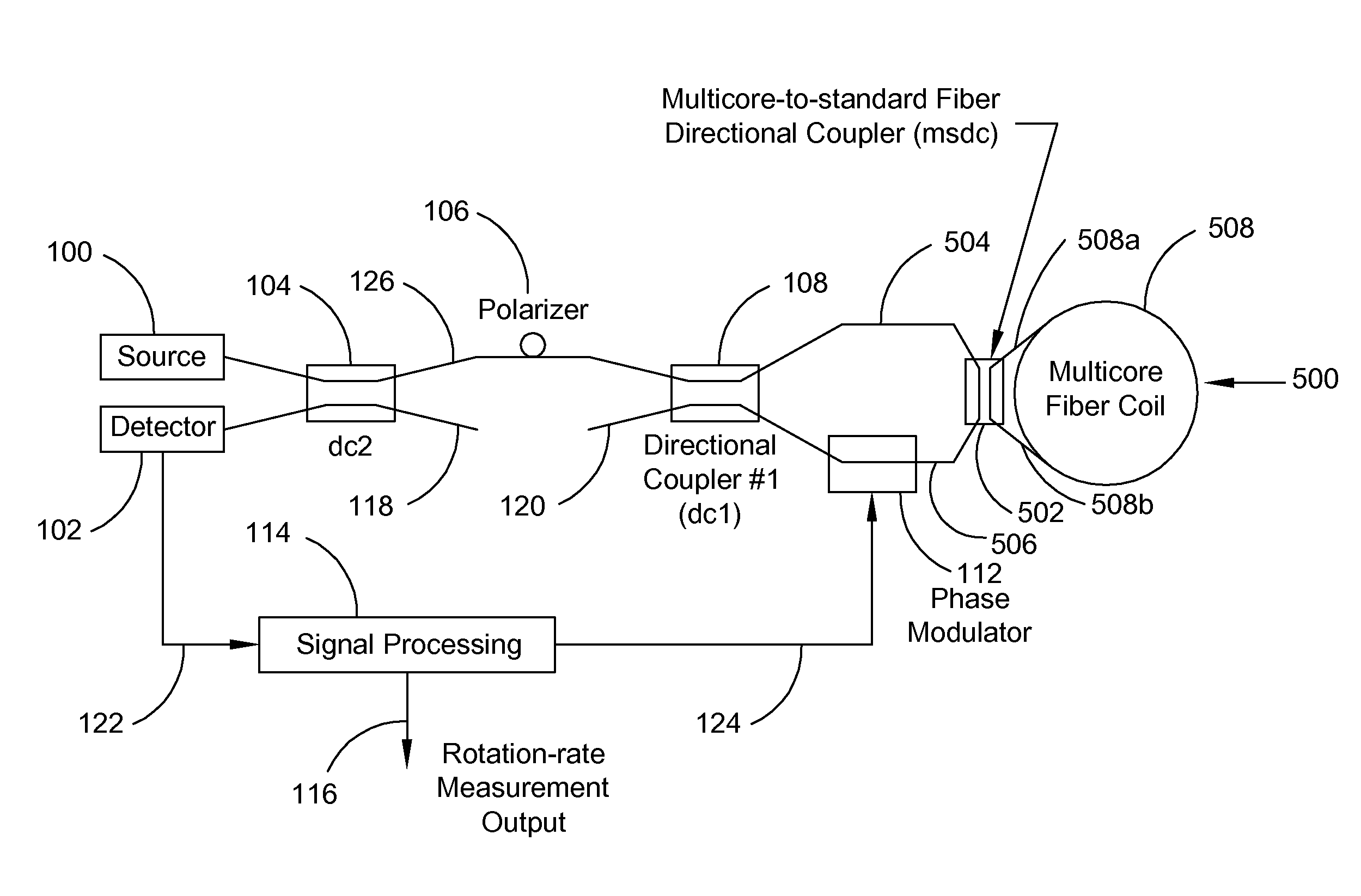
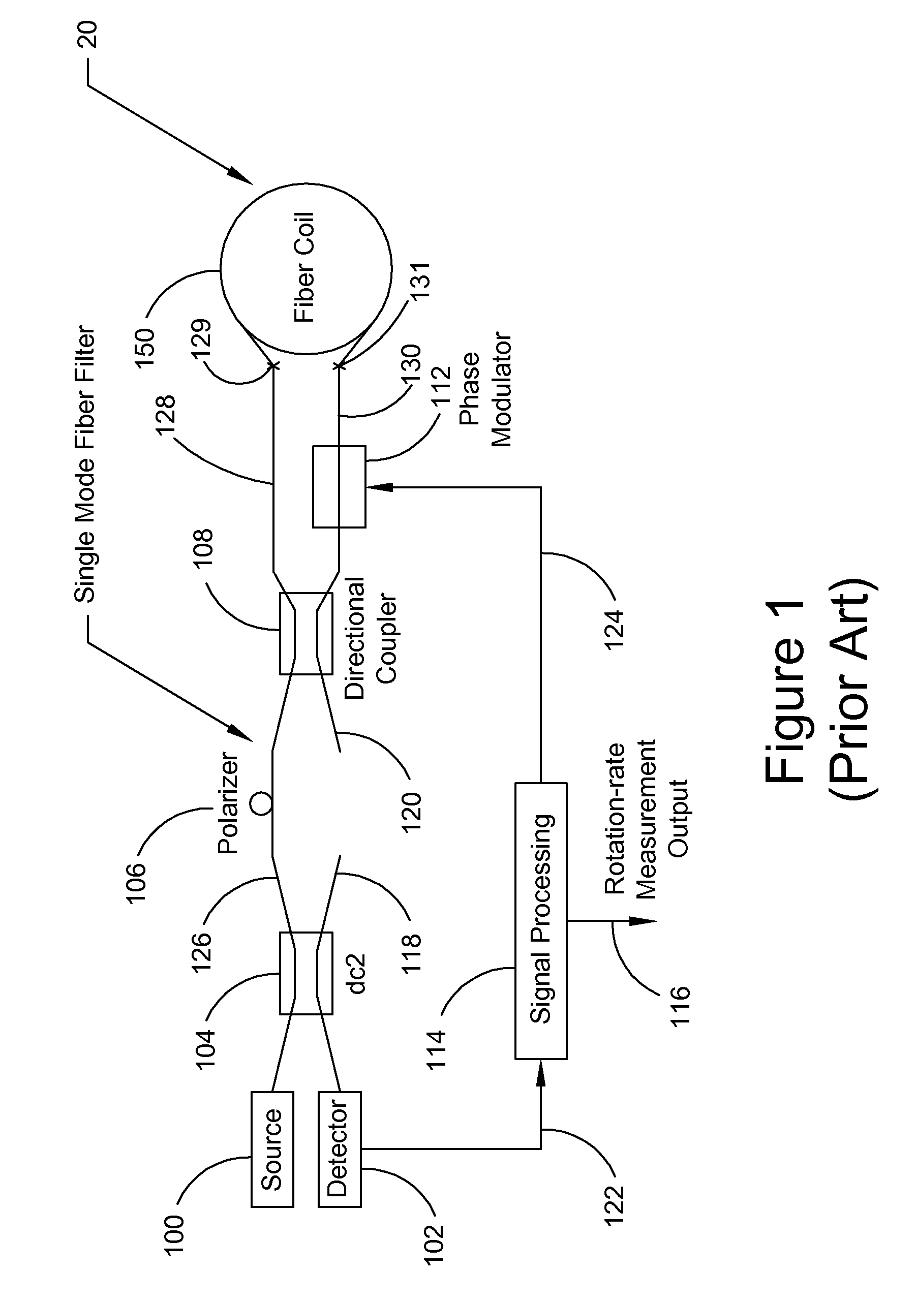
[0029]A general block diagram of a FOG known in the prior art is depicted in FIG. 1 as aforedescribed in the Background. As is common in fiber optic rate sensors, a light source 100 provides a source light wave that is passed through a directional coupler 104, polarizer 106 via a single mode fiber 126, and a second directional coupler 108 that splits the impinging source light wave into (i) a first light wave that enters a first end 129 of a single mode fiber that is wound into a fiber coil 150 via fiber 128, and (ii) a second light wave that passes through a phase modulator 112 and fiber 130 before entering the second end 131 of the single mode fiber that is wound into the fiber coil 150.

[0030]The first and second light waves, having traversed the same exact optical path of the single mode fiber or single waveguide of the fiber coil 150, are again passed through the directional couple 108, polarizer 106, and directional coupler 104, where a portion of each of the light waves is dir...


PUM


Abstract

An interferometer employed, in part, as a Sagnac interferometer or fiber optic gyro (FOG) includes a light source (100) that provides a source light wave that is split into first and second light waves that are directed to traverse a defined optical loop path (508, 500) in opposite directions. The defined optical loop path (508, 500) in accordance with the present invention is provided by multiple waveguides wound into a coil such that the opposite traveling first and second light waves serially travel through all of the waveguides in opposite directions around the optical loop path.

Description

FIELD OF THE INVENTION[0001]The present invention relates, in general, to a Sagnac Interferometer, and more particularly one that is useful in a fiber optic rotation rate sensor, commonly referred to as a fiber optic gyroscope (FOG), employing a wound coil of many turns of a continuous optical fiber, defining an optical loop path, for passing a light wave therethrough.BACKGROUND OF THE PRESENT INVENTION[0002]The heart of the fiber optic rotation rate sensor or gyroscope (hereafter, simply FOG) is well known in the art is the Sagnac interferometer, briefly illustrated in FIG. 1. The Sagnac interferometer in its simplest form consists of a single directional coupler 108, e.g. a beam splitter, and an optical path that in our case amounts to a length of optical fiber formed into a loop 20, 1 turn or multiple turns, respectively. The directional coupler 108 is used to split an impinging light wave derived from a light source 100 into two waves, but it can also be used to combine two wave...

Claims


Application Information

Patent Timeline
Patent Type & Authority Patents(United States)
IPC IPC(8): G01C19/72
CPCG01C19/72G01C19/64G01B9/02049G01B9/0209
Inventor BERGH, RALPH A.
Owner BERGH RALPH A
Why Eureka
Try Eureka