
Method for producing a flexi-rigid printed circuit board and flexi-rigid printed circuit board

a printed circuit board and rigid technology, applied in the direction of printed circuit aspects, electrical equipment, lamination, etc., can solve the problems of counteracting the intended miniaturization, reducing the registering accuracy required, etc., and achieve the effect of improving processing or working in further and enhancing registering accuracy

Active Publication Date: 2013-08-06
AT & S AUSTRIA TECH & SYSTTECHN AG
View PDF15 Cites 7 Cited by
  • Summary
  • Abstract
  • Description
  • Claims
  • Application Information

AI Technical Summary

Benefits of technology

This approach reduces the overall thickness of the circuit board, enhances registering accuracy, and simplifies the production process by allowing for precise application of adhesives, resulting in reliable connections with fewer processing steps and improved miniaturization capabilities.

Problems solved by technology

Such thick layers not only counteract the intended miniaturization in the fabrication of multilayer circuit boards, but also entail losses of the registering accuracy required for subsequent laser borehole geometries for the formation of microvias and accordingly narrowly spaced-apart connection sites.
Such thick, known layers of non-conductive materials, or dielectric layers, moreover, involve additional processing or process steps and / or more complex designs for the production of the connections required between the rigid and flexible portions of circuit boards.

Method used


Image

  • Method for producing a flexi-rigid printed circuit board and flexi-rigid printed circuit board
  • Method for producing a flexi-rigid printed circuit board and flexi-rigid printed circuit board
  • Method for producing a flexi-rigid printed circuit board and flexi-rigid printed circuit board

Examples


Embodiment Construction

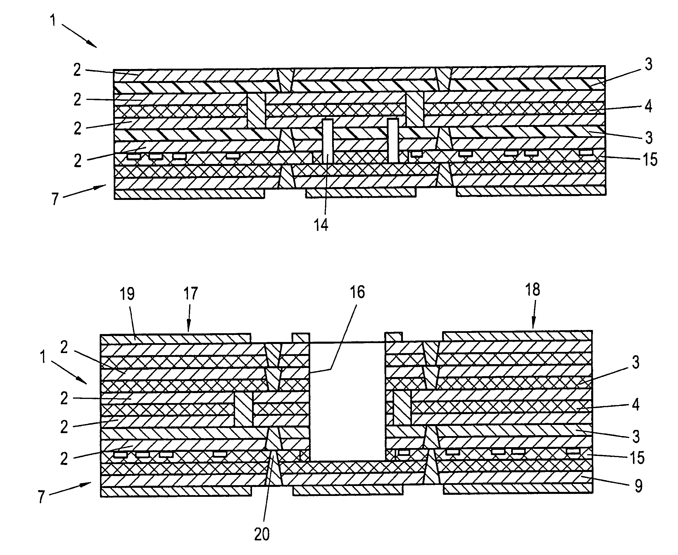
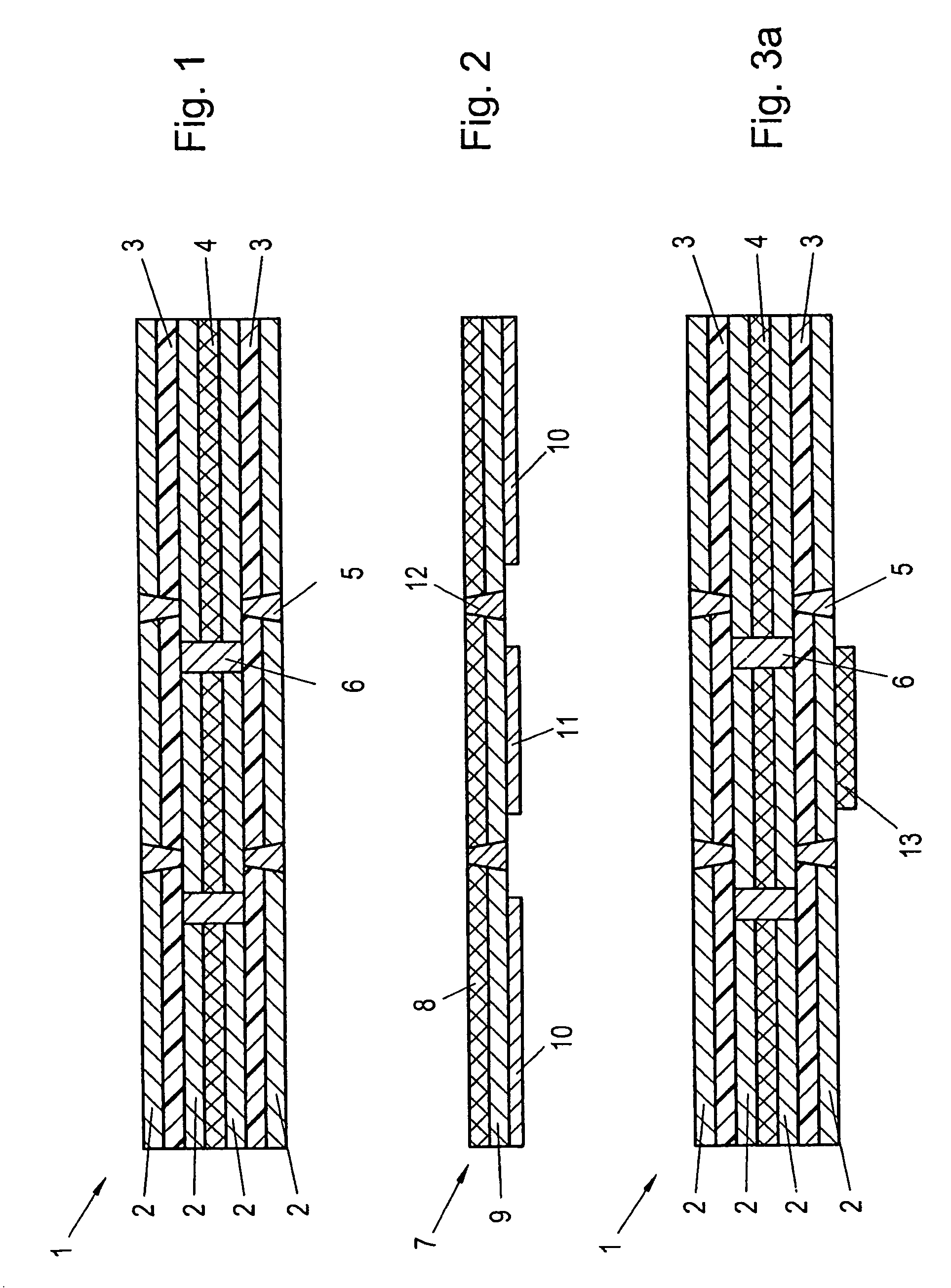
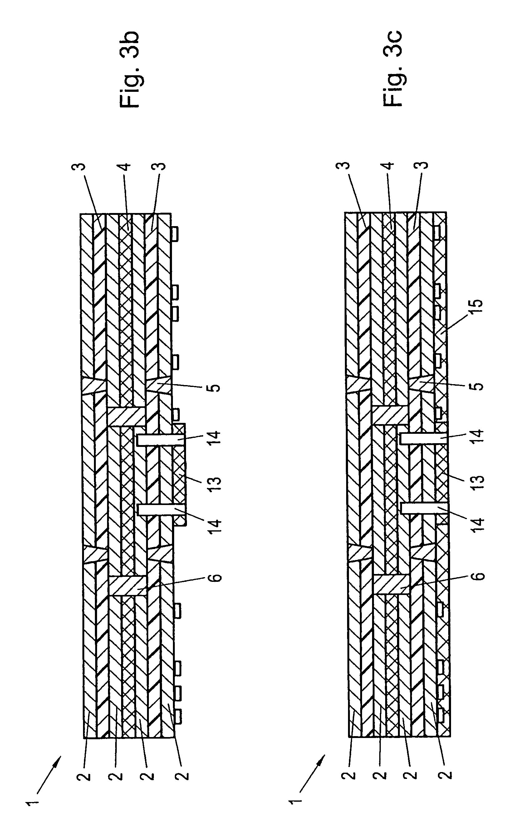
[0024]FIG. 1 is a schematic illustration of a rigid portion 1 of a rigid-flexible circuit board to be produced subsequently, said rigid portion or zone 1 being multilayered. Copper coats 2 are respectively separated from each other by a prepreg layer 3 and a core 4. Connections between the individual copper layers 2 are indicated via microvias 5 and passages 6, respectively.

[0025]FIG. 2 depicts a schematic section through a flexible portion or zone 7 of a rigid-flexible circuit board to be produced, wherein, in addition to a flexible laminate layer 8, a copper layer 9 and solder masks 10 and 11, respectively, are indicated. For a connection to be subsequently formed with subportions of the rigid portion 1 of the circuit board, which are to be connected therewith, microvias or passages 12 are indicated.

[0026]In a first method step as in accordance with FIG. 3a, a first adhesive layer 13, which will be completely cured subsequently, is selectively applied on the rigid portion of the r...


PUM

PropertyMeasurementUnit
thicknessaaaaaaaaaa
temperaturesaaaaaaaaaa
thicknessaaaaaaaaaa

Abstract

The invention relates to a method for producing a flexi-rigid printed circuit board, at least one rigid zone (1, 17, 18) of a printed circuit board being connected via a layer of non-conducting material or a dielectric layer (13, 15) to at least one flexible zone (7) of the printed circuit board, the at least one rigid zone being connected to the flexible zone (7) of the printed circuit board, the rigid zone (1) of the printed circuit board then being cut through and a connection between the separate, rigid partial zones (17, 18) of the printed circuit board being established via the flexible zone (7) that is connected thereto. According to the invention, the connection between the at least one rigid zone (1, 17, 18) of the printed circuit board and the at least one flexible zone (7) of the printed circuit board is established by bonding prior to cutting the rigid zone. The invention also relates to a flexi-rigid printed circuit board of the above type which allows increased registration accuracy and is easy to produce and has a reduced layer thickness of the connection (15) between the at least one rigid zone (1, 17, 18) and the flexible zone (7) of the printed circuit board.

Description

[0001]This is a national stage of PCT / AT08 / 000,030 filed Jan. 30, 2008 and published in German, which has a priority of Austria no. GM 99 / 2007 filed Feb. 16, 2007, hereby incorporated by reference.FIELD OF THE INVENTION[0002]The present invention relates to a method for producing a rigid-flexible circuit board, wherein at least one rigid portion or zone of a printed circuit board is connected with at least one flexible portion or zone of the printed circuit board via a layer of non-conductive material or dielectric layer, wherein, after having connected the at least one rigid and flexible portions of the circuit board, the rigid portion of the circuit board is divided and a connection between the mutually separated rigid subportions or partial zones of the circuit board is produced via the flexible portion connected therewith, wherein the connection between the at least one rigid portion of the circuit board and the at least one flexible portion of the circuit board is realized by a...

Claims


Application Information

Patent Timeline
Patent Type & Authority Patents(United States)
IPC IPC(8): H05K1/00B32B38/04
CPCH05K3/4691H05K3/4626H05K3/4652H05K3/4655Y10T156/1062H05K2201/0909H05K2201/09127H05K2203/1476H05K2201/0195H05K3/46
Inventor STAHR, JOHANNESLEITGEB, MARKUS
Owner AT & S AUSTRIA TECH & SYSTTECHN AG
Learn More