Circuit for thermal protection in audio power amplifier and method thereof

a technology for audio power amplifiers and circuits, applied in emergency protection circuit arrangements, low frequency amplifiers, gain control, etc., can solve the problems of user discomfort on user's hearing, common damage to output stage amplifiers, etc., and achieve the effect of preventing damage to audio amplifiers

Inactive Publication Date: 2013-08-13
GENERALPLUS TECH INC
View PDF6 Cites 11 Cited by
  • Summary
  • Abstract
  • Description
  • Claims
  • Application Information

AI Technical Summary

Benefits of technology

[0008]It is therefore an objective of the present invention to provide a thermal protecting circuit for an audio amplifier such that the damage of the audio amplifier is prevented.
[0009]Another objection of the present invention is to provide a audio amplifier such that the uncomfortable feeling on user's hearing can be prevented and also the audio amplifier can be normally operated.
[0019]The spirit of the present invention is to integrate the gain adjusting mechanism and the temperature protect. When the temperature is greater than a preset threshold, the gain would be reduced with the increment of the temperature, such that the audio interrupt is avoided and the uncomfortable feeling on user's hearing can be reduced.

Problems solved by technology

However, the heat sink may not completely absorb the heat generated by the output stage amplifier 102, Thus, the damage of the output stage amplifier 102 commonly occurs when the output stage amplifier 102 is overheat.
However, users would have a uncomfortable feeling on user's hearing.

Method used


Image

  • Circuit for thermal protection in audio power amplifier and method thereof
  • Circuit for thermal protection in audio power amplifier and method thereof
  • Circuit for thermal protection in audio power amplifier and method thereof

Examples


first embodiment

The First Embodiment

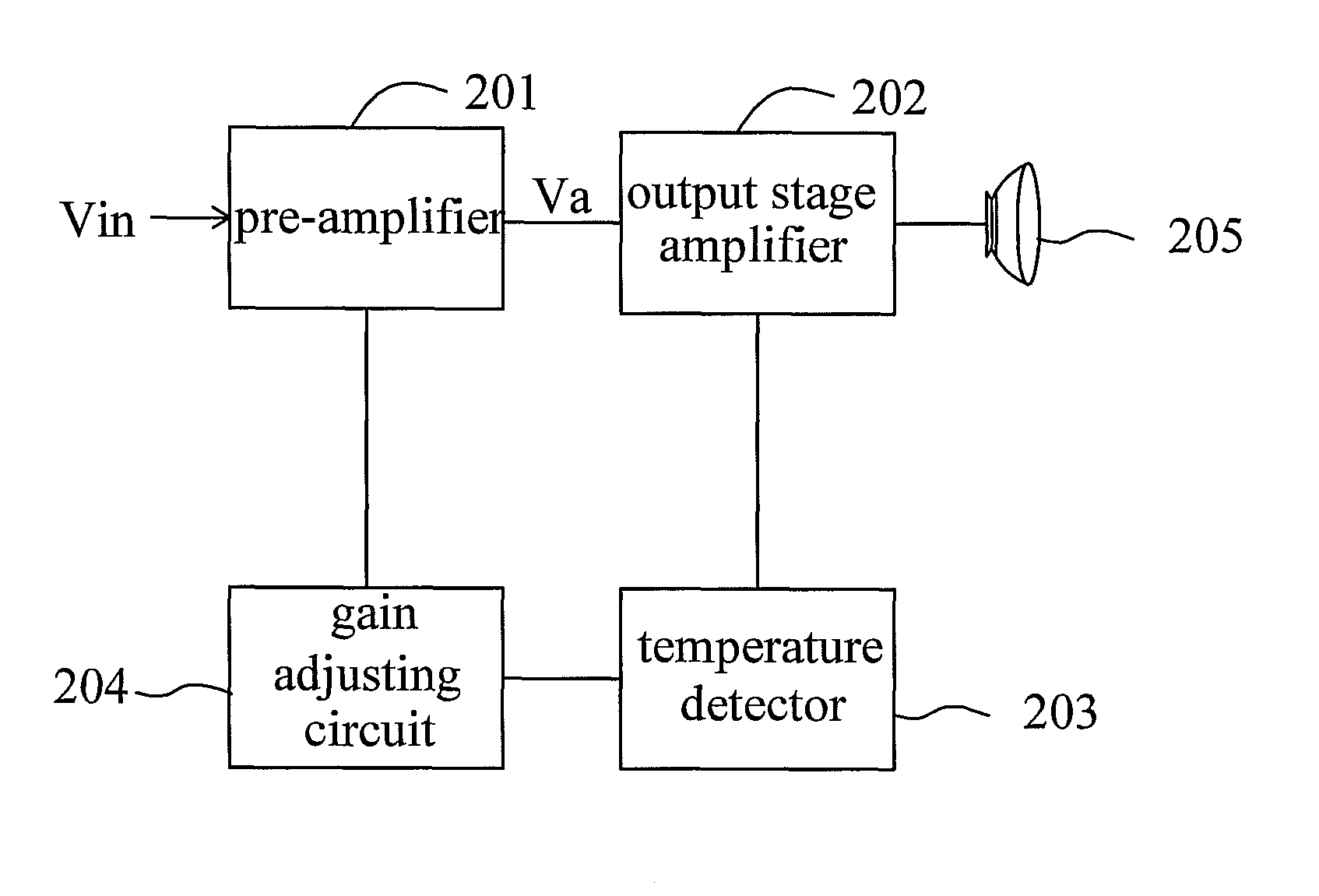
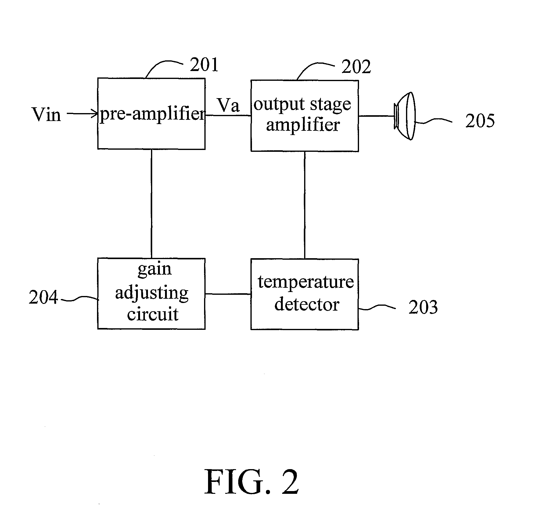
[0032]FIG. 2 illustrates a circuit diagram depicting an audio amplifier with a built-in thermal protecting circuit according to a first embodiment of the present invention. Referring to FIG. 2, the audio amplifier includes a pre-amplifier 201, an output stage amplifier 202, a temperature detector 203 and a gain adjusting circuit 204. The pre-amplifier 201 receives an audio signal Vin for amplifying the audio signal to generate an amplified audio signal Va. The output stage amplifier 202 receives the amplified audio signal Va for driving the loading 205, such as speaker. The temperature detector 203 is used for detecting the temperature of the output stage amplifier 202 to output a temperature signal. Since the output stage amplifier 203 is used for driving the load such that the power consumption thereof is relatively greater than that of the other circuits in the audio amplifier. Thus, the main heat source of the audio amplifier would be the output stage amplifi...

second embodiment

The Second Embodiment

[0035]FIG. 3 illustrates a circuit diagram depicting an audio amplifier with a built-in thermal protecting circuit according to a second embodiment of the present invention. Referring to FIG. 3, this embodiment discloses the detail circuit of the first embodiment, wherein the pre-amplifier 201 is only illustrated the inputs of the differential pair, the adjustable current source 302 is used for example of the gain adjusting circuit 204. In this embodiment, the adjustable current source 302 is implemented by a N-type MOSFET (Metal Oxide Semiconductor Field Effect Transistor). According to the circuit disclosed in this embodiment, the gain of the pre-amplifier 201 is determined by the trans-conductor (gm). The current I301 is adjusted, and the trans-conductor (gm) is also adjusted, and the gain of whole circuit is therefore adjusted. Thus, in the present embodiment, when the temperature is increased, the voltage Vb is decreased as the increasing of the temperature...

third embodiment

The Third Embodiment

[0036]FIG. 4 illustrates a circuit diagram depicting an audio amplifier with a built-in thermal protecting circuit according to a third embodiment of the present invention. Referring to FIG. 4, the difference between FIG. 4 and FIG. 2 is that the gain adjusting circuit 204 is coupled between the pre-amplifier 201 and the output stage amplifier 202, and the gain adjusting circuit 204 is implemented as an attenuator 404. the purpose of the design mainly is to attenuating the amplitude of the amplified audio signal Va outputting from the pre-amplifier 201. When the temperature increases, the amplitude of the signal Va would be reduced such that the output stage amplifier 202 drives the speaker 205 with smaller driving current. Since the driving current is reduced, the temperature would thereby reduce.


PUM


Abstract

The present invention relates to audio amplifier and a method for protecting the audio amplifier. The audio amplifier includes a pre-amp circuit, an output stage power amplifier, a temperature detector and a gain adjusting circuit. The pre-amp circuit receives an audio signal for amplifying the audio signal to generate an amplified audio signal. The output stage power amplifier receives the amplified audio signal to drive a load. The temperature detector is used for detecting a temperature of the output stage power amplifier to output a temperature signal. The gain adjusting circuit adjusts amplitude of the amplified audio signal of the pre-amp circuit according to the temperature signal.

Description

[0001]This application claims the benefit of TW Application No. 099134659 filed on Oct. 16, 2010, the content of which is hereby incorporated by reference.BACKGROUND OF THE INVENTION[0002]1. Field of Invention[0003]The present invention relates in general to an over-temperature protection circuit, and more particularly to a circuit for thermal protection in audio power amplifier and a method thereof.[0004]2. Related Art[0005]The purpose of the audio amplifier is to reconstruct the input audio signal to output to the element for generating audio. The frequency range of the audio is about 20 Hz to 20 KHz. Thus, the audio amplifier must have a good frequency response in the abovementioned frequency range. According to the different applications, the necessary powers of the audio amplifier are greatly different. For example, the application of milli-watts may be earphone, the application of watts may be speaker for TV or PC, the application of tens of watts may be automotive audio syste...

Claims


Application Information

Patent Timeline
Patent Type & Authority Patents(United States)
IPC IPC(8): H02H7/20
CPCH03F1/301H03F3/187H03F3/45183H03G3/3005H03G3/3026H03F2200/03H03F2200/408H03F2200/411H03F2200/447H03F2200/468H03F2203/45528H03F2203/45534H03F2203/45536H03F2203/45594H03F2203/45616H03F2203/45618
Inventor LEE, KUNG-WANGLIAO, TUNG-TSAI
Owner GENERALPLUS TECH INC
Why Eureka
Try Eureka