
Hybrid wave energy plant for electricity generation

a technology of hybrid wave energy and electricity generation, which is applied in the direction of sea energy generation, couplings, engine fuctions, etc., can solve the problems of prohibitive cost of high amount of electricity generation

Inactive Publication Date: 2013-08-20
SEAHORSE WAVE ENERGY ENERGIA DAS ONDAS
View PDF15 Cites 1 Cited by
  • Summary
  • Abstract
  • Description
  • Claims
  • Application Information

AI Technical Summary

Benefits of technology

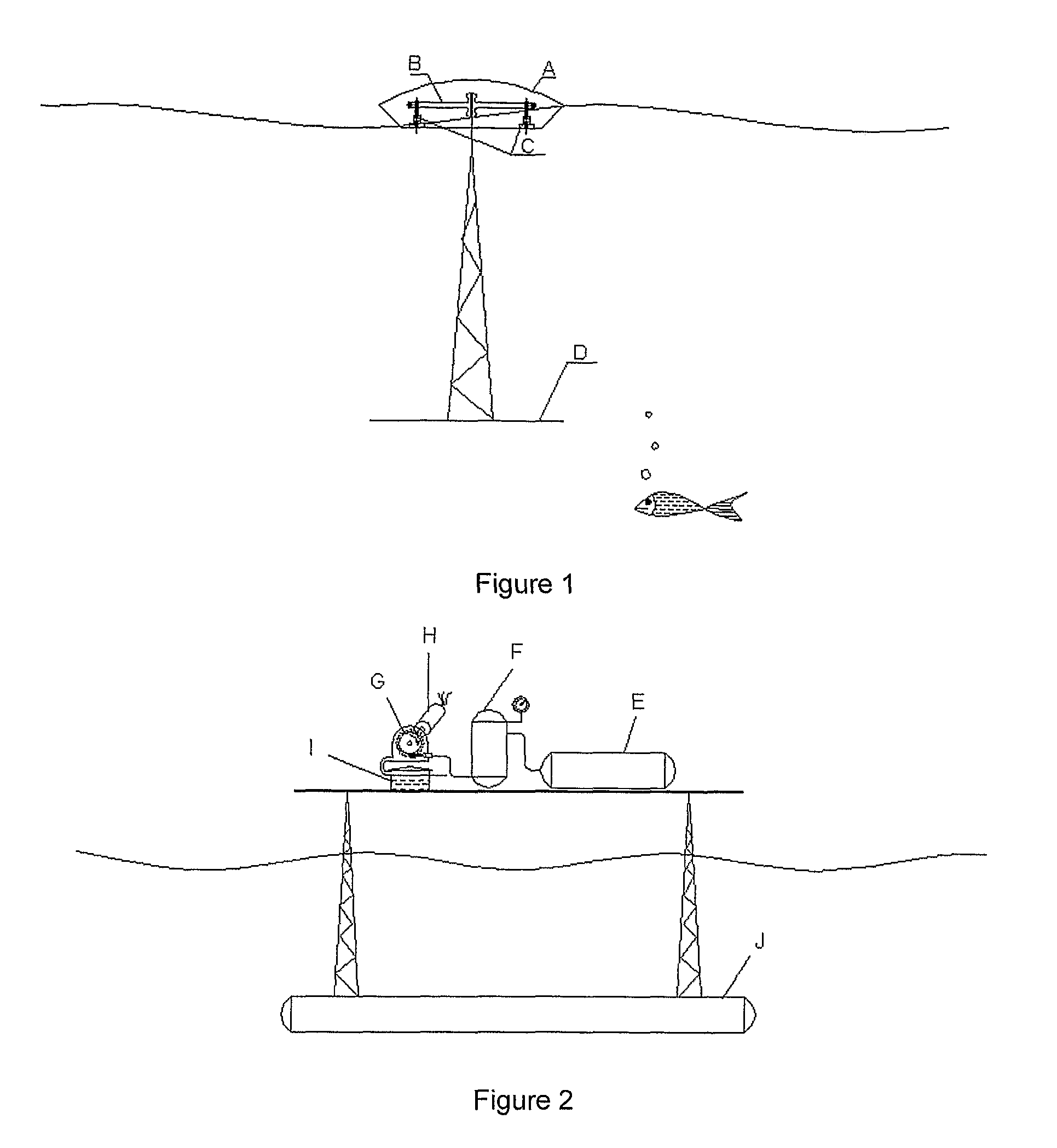
The plant described in this patent operates in a closed circuit, using a pump to move water from a tank to a hydraulic accumulator. This accumulator maintains a constant pressure level during operation. The main role of the accumulator is to guarantee the stability of the pressure level. An electronic control monitors the turbine rotation to ensure efficient and regular electricity generation. The high pressure valve is designed to control power output during changes in electricity demand or sea conditions, and can also stop the plant operation in predictive maintenance or emergency situations. The technical effect of this design is a more stable and efficient plant that can adjust to changing conditions and prevent damage or malfunction.

Problems solved by technology

This procedure may lead to a prohibitive cost for high amount of electricity generation.

Method used


Image

  • Hybrid wave energy plant for electricity generation
  • Hybrid wave energy plant for electricity generation
  • Hybrid wave energy plant for electricity generation

Examples


Embodiment Construction

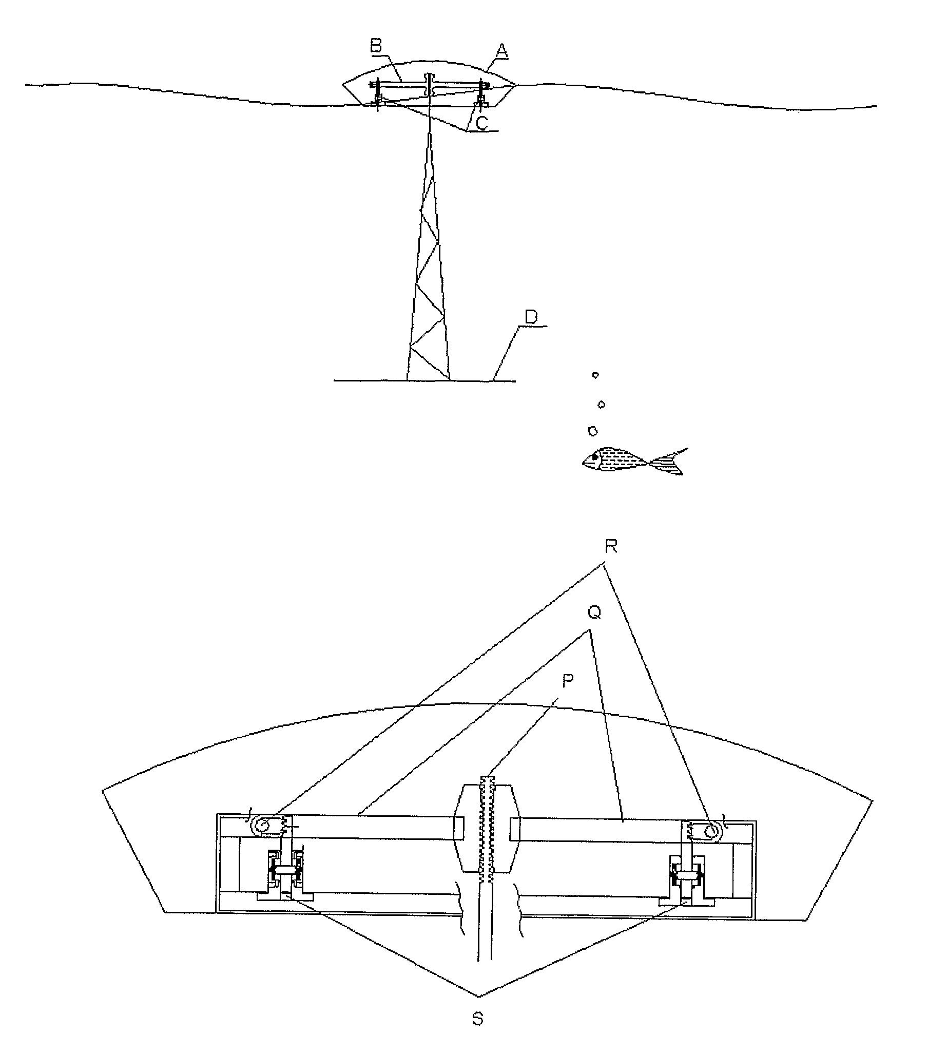
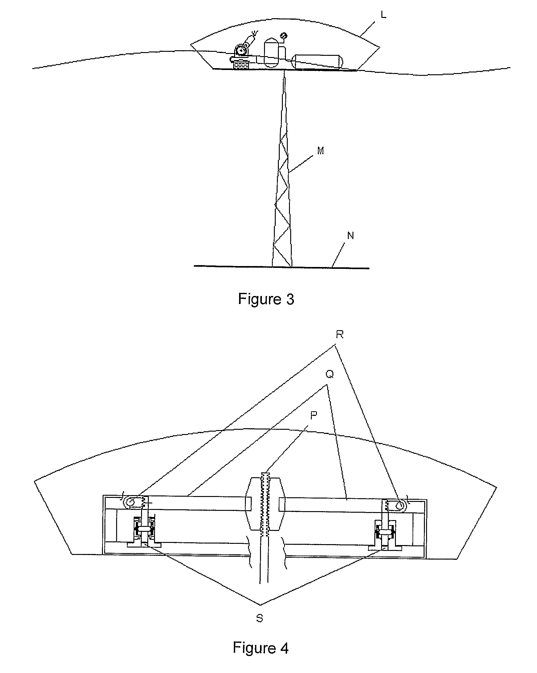
[0019]The present invention describes a wave energy device that is composed by three systems: pumping modules, high pressure system and electricity generation group. Every pumping module has a floater, a damper, two hydraulic pumps and a mechanical load amplifier. The high pressure system contains the hyperbaric chamber, and the hydro pneumatic accumulator. The generation group is composed by the turbine, electric generator and the plant control module.

[0020]For offshore applications a damper system is employed in order to maximize the relative motion between load amplifier and the pumps.

Description of the Operational Mode of the Plant and of the Equipment Parts

[0021]The present invention describes a wave energy converter that operates through the action of the sea waves on cylindrical shape floaters named pumping modules. These modules move up and down pumping water in high pressure. Each floater induces a load between the damper and the inside mechanical load amplifier system. Thi...


PUM


Abstract

The innovation herein proposed describes a plant to produce electricity by the sea waves. The plant is designed to be installed on shore, near shore and offshore scenarios: on the coast line, in shallow waters and in deep waters. The plant is operated by action of the sea waves on a series of floaters (A). The resultant force on each floater (A) acts on a mechanical load amplifier (B) which moves two vertical high pressure piston pumps (C). These pumps (C) send pressurized fresh water to a hyperbaric system (E). The hyperbaric system (E) supplies an outflow water jet through a controlled valve that moves a conventional turbine (G). This turbine (G) connected to the electric generator (H) produce electricity.

Description

TECHNICAL FIELD[0001]The proposed concept deals with an ocean wave energy device for electricity generation. It is composed by three main systems working together: the pumping modules, the high pressure system and the electricity generation group. Each pumping module is composed by a floater, a damper, two hydraulic pumps and a mechanical load amplifier. The high pressure system consists of both hyperbaric chamber and hydraulic accumulator. The generation group involves the turbine, the electric generator and the plant control module.PREVIOUS TECHNIQUES[0002]In the year 1799 in France, the wave energy was employed directly to drive pumps, mills and other heavy mechanisms. Since then, experiences with different concepts have been carried out worldwide.[0003]Following the oil crisis of the 70's, the scientific research has provided significant improvements to the technology for extracting increased amounts of electricity from wave energy, particularly in Europe.[0004]Currently the ele...

Claims


Application Information

Patent Timeline
Patent Type & Authority Patents(United States)
IPC IPC(8): F03B13/18
CPCF03B13/186F05B2240/40F05B2240/911F05B2260/4031Y02E10/38Y02E20/16F05B2240/93F05B2240/95F03B13/187F03B13/20Y02E10/30
Inventor DA COSTA, PAULO ROBERTO
Owner SEAHORSE WAVE ENERGY ENERGIA DAS ONDAS
Learn More