Discrete contact MR bio-sensor with magnetic label field alignment

a biosensor and magnetic label technology, applied in the field of microparticle assays, can solve the problems of uncontrollable label binding, unfavorable one-on-one binding, and large randomness of binding sites, so as to minimize the effect of label variation, reduce noise, and eliminate signal fluctuations

Active Publication Date: 2013-08-20
HEADWAY TECH INC
View PDF8 Cites 15 Cited by
  • Summary
  • Abstract
  • Description
  • Claims
  • Application Information

AI Technical Summary

Benefits of technology

[0038]Another object of at least one embodiment of the present invention has been to minimize label-to-sensor physical distance variations by use of controlled field gradient and physical confinement structure design to enhance the precision of label localization.
[0039]Still another object of at least one embodiment of the present invention has been to reduce magnetic noise by minimizing the effects of free magnetic edge charges through use of a continuous MR sensor and / or edge pinning with bias field.
[0041]A still further object of at least one embodiment of the present invention has been to relieve the requirement of large sensor size.
[0042]Yet another object of at least one embodiment of the present invention has been to enable biological cell detection by MR sensors without needing to remove unbound magnetic labels or particles

Problems solved by technology

A key problem facing the current and prior art is that which binding sites get labeled is largely random.
One-on-one binding of this sort is, however, not readily achievable in practice.
Additionally, labels may quite likely land on the edge of, or even between, the sensors, This uncontrolled binding of the labels produces signal variations due to the different number of labels on each sensor.
Thus, the correlation is further blurred and sensing accuracy is more reduced.
Additionally, since most of the large sensors used in prior arts do not have a hard bias structure to pin the free layer magnetization, for example as in BARC, domain structures are very likely to form at the sensor edges, leading to low frequency large amplitude Barkhausen noise.
With all the noise and fluctuation sources acting together, the population estimation accuracy can be severely limited and the fluctuations can become large enough to inhibit practical binding assay applications that are based on the detection of the absolute field strength.
However, the patterned MR sensors used for assays have intrinsic signal variations between themselves due to fabrication uncertainty.
Also, due to the same uncertainty, the sensor cannot be too small or the sensor to sensor signal and response variation will be too large.
Additionally, the large size of the transistors used to power each sensor individually limits the maximum sensor areal density.
Therefore, a limitation on the spatially resolution of the cell matrix exists.
More importantly, since the patterned MR sensors in the assays do not include a hard bias structure, the MR sensors may have large sensitivity fluctuations because of unpinned edges and leads larger sensitivity variations limits the detection accuracy.
Detection aided by a 2D mapping of the MR signal is limited by the spatial resolution from the minimal sensor size and sensor to sensor distance.
The large sensor to sensor signal variation, sensor intrinsic signal fluctuation due to fabrication and large noise from unbiased MR structures are also serious challenges in the prior art.

Method used


Image

  • Discrete contact MR bio-sensor with magnetic label field alignment
  • Discrete contact MR bio-sensor with magnetic label field alignment
  • Discrete contact MR bio-sensor with magnetic label field alignment

Examples


embodiment 2

[0095]Optionally, layer 99 may be above surface 97 before structure 92 is added on top. , edge 98 connects bottom surface 11 and top surface 97. Protection layer 98 is on surfaces 11, 94 and, optionally, 97. On top of layer 98, there is, optionally, another biological layer 99, which serves the purpose of selectively binding the target molecules, cell or other biological entities on the surfaces. Layers 98 and 99 can be coated over the entire confinement structure.

[0096]FIG. 9c shows optional cover structure 91 that is physically fixed on top of surface 97 and layer 98, forming a closure space together with edges 94 and floor 11. This closure helps to confine liquid samples within the test space. Optionally, layer 99 may be deposited over surface 97 before structure 91 is added.[0097](1) Sample Injection

embodiment 5

[0098]The liquid sample can be dripped directly into the testing structure or it can be made to flow into testing structure by exerting pressure or by capillary force of conducting paths. The magnetic labels or magnetic label coated biological entities are attracted into the testing confinement by the applied magnetic field with or without a funneling structure 20 as in Embodiments 4A4C.[0099](2) Sample Preparation

embodiment 6

[0100]The sample is a liquid containing magnetic label coated biological entities. Free labels may also be present in the sample.[0101](3) Field Application

[0102]Embodiment 7A—The magnetic field that magnetizes the magnetic labels is generated by permanent magnets. A gradient near the edge of the field serves to line up the magnetic labels (or biological entities coated with magnetic labels) against the floor and the wall. Said gradient is determined by the shape of the permanent magnets. An example (not limiting) is a thin cylinder shaped permanent magnet whose magnetization is perpendicular to the cylinder's flat surface. There is optionally a soft magnetic structure on top of the permanent magnet structure to assist magnetic field and gradient generation. Additional options are to taper the magnet shape in order to enhance the gradient and to include an embedded soft magnetic material structure within the substrate. The embedded structure can be magnetized by the permanent magnet...


PUM

PropertyMeasurementUnit
particle sizeaaaaaaaaaa
diameteraaaaaaaaaa
diameteraaaaaaaaaa

Abstract

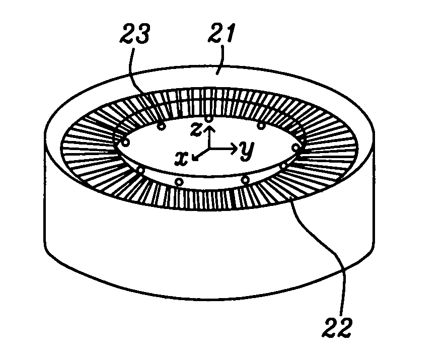
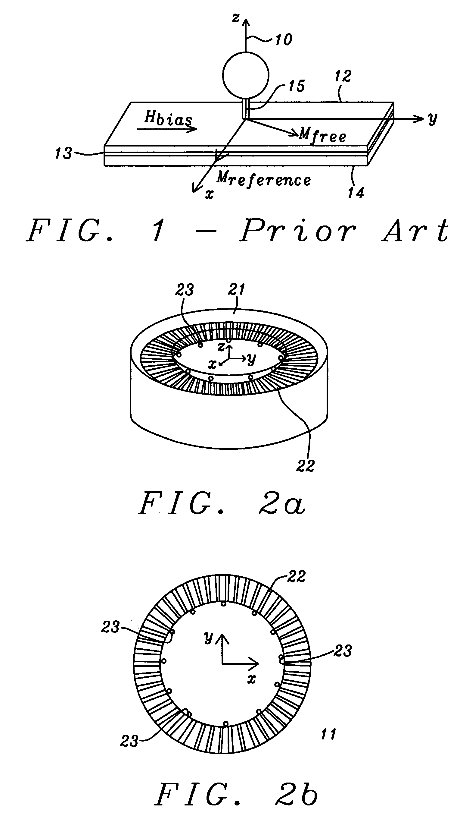
The invention describes a family of sensors for assaying macro-molecules and / or biological cells in solution. Each sensor has the form of a well (a hollow cylinder having a floor but no lid) or a trench whose walls comprise a plurality of GMR or TMR devices. Suitably shaped magnets located below each well's floor pull labeled particles into the well / trench and up against the inner wall where a field gradient orients them for optimum detection. Any unattached labels that happen to also be in the well / trench are removed through suitably sized holes in the floor.

Description

FIELD OF THE INVENTION[0001]The invention relates to the general field of micro-particle assays with particular reference to detection and identification of all such particles within the environment being investigated.BACKGROUND OF THE INVENTION[0002]It is a widely adopted sample separation method to selectively bind magnetic labels to biological cells and molecules and utilize the labels' magnetic property to separate the cells and molecules from the biological solution with an externally applied magnetic field. The selective bindings commonly used are polynucleic acid bindings or hybridizations (RNA and DNA), many types of ligand to receptor bindings, as well as antibody to antigen bindings.[0003]With the same biological binding process, it has been a primary purpose of many prior arts to detect the magnetic field emanating from the bound magnetic labels with magneto-resistive (MR) sensors. Thus, the detection and counting of the cells and molecules can be accomplished without usi...

Claims


Application Information

Patent Timeline
Patent Type & Authority Patents(United States)
IPC IPC(8): G01N33/553G01N33/53
CPCB82Y25/00G01N27/745G01R33/093G01R33/1269
Inventor ZHOU, YUCHEN
Owner HEADWAY TECH INC
Why Eureka
Try Eureka