
Double leading edge airfoil for wind turbine blade root

a technology of airfoil and wind turbine blade, which is applied in the direction of propellers, propulsive elements, water-acting propulsive elements, etc., can solve the problems of low lift coefficient value and none of the known designs producing fully satisfactory results, so as to improve the performance of the wind turbine blade

Active Publication Date: 2013-08-27
GAMESA INNOVATION & TECH SA
View PDF7 Cites 1 Cited by
  • Summary
  • Abstract
  • Description
  • Claims
  • Application Information

AI Technical Summary

Benefits of technology

The present invention provides a wind turbine blade with an improved profile in the root region, which enhances its performance. Additionally, the blade has an aerodynamically optimized profile in the root region, which enables cost-efficient manufacturing.

Problems solved by technology

However, the value of the lift coefficient is usually moderate in this type of profiles and occurs at moderate low angles of attack.
However the manufacturing process is limited to certain values in chords and twist, so values for these variables are therefore restricted in order to optimize overall costs.
None of known designs produces fully satisfactory results, therefore a continuing need exists for wind turbine blades with an aerodynamic optimised profile in the root region.

Method used


Image

  • Double leading edge airfoil for wind turbine blade root
  • Double leading edge airfoil for wind turbine blade root
  • Double leading edge airfoil for wind turbine blade root

Examples


Embodiment Construction

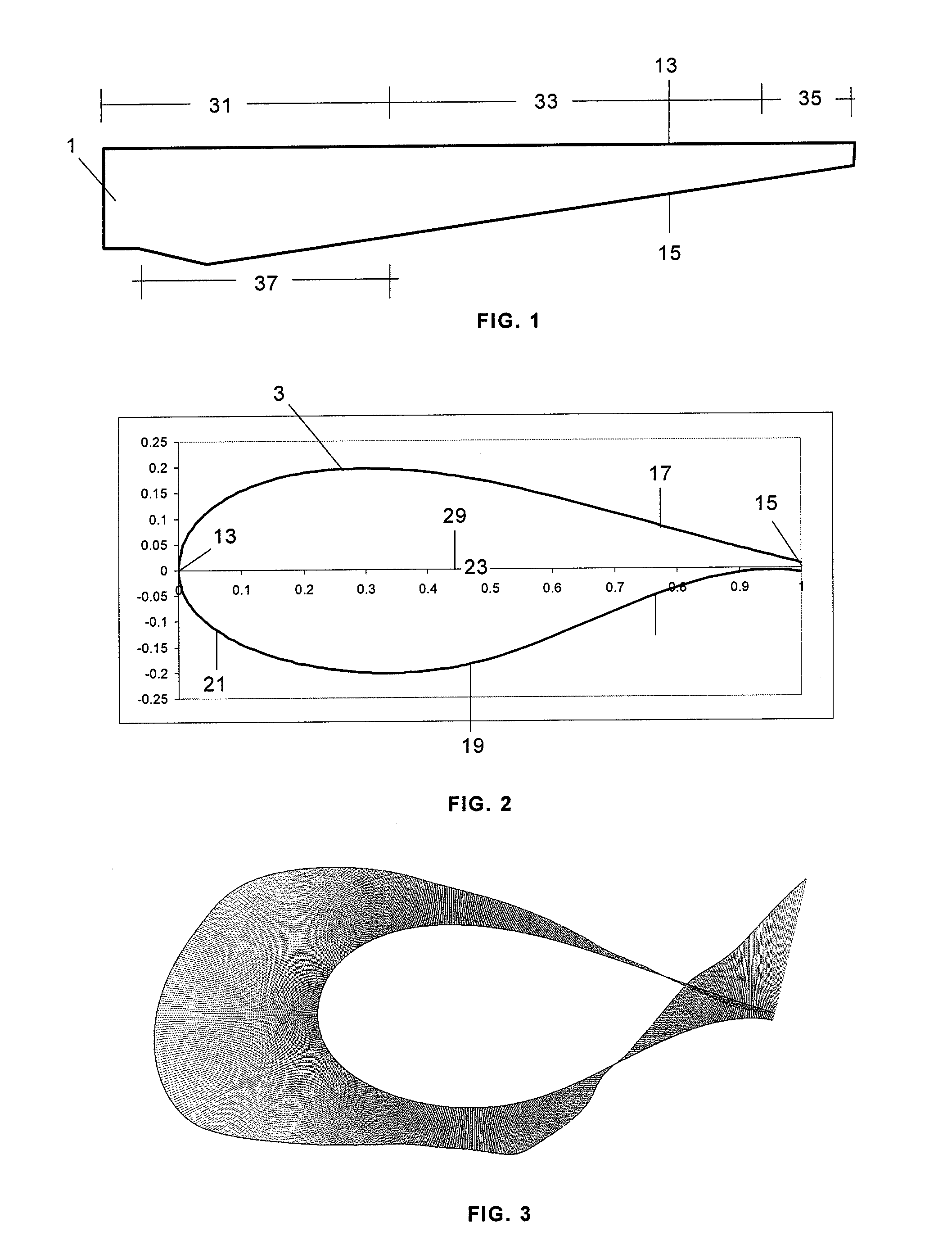
[0018]As it can be seen in FIG. 1 a typical wind turbine blade 1 has three regions: the root region 31 which includes the portion of the blade 1 that is close to the rotor hub, the tip region 35 which includes the portion of the blade 1 that is most distant from the rotor hub, and the mid-span region 33 between the root region 31 and the tip region 35.

[0019]The length of the root region 31 is approximately 10%-50% of the blade length. The length of the mid-span region 33 is approximately 80%-40% of the blade length. The length of the tip region 35 is approximately 10% of the blade length.

[0020]The shape, contour and length of the blades of a wind turbine determine, in large part, the efficiency and power production capabilities of the wind turbine. As it is well known the rotor hub is mounted on a rotatable shaft connected either directly or through a gearbox to drive an electric generator located in a nacelle for generating electric energy that can be transmitted to an utility grid...


PUM


Abstract

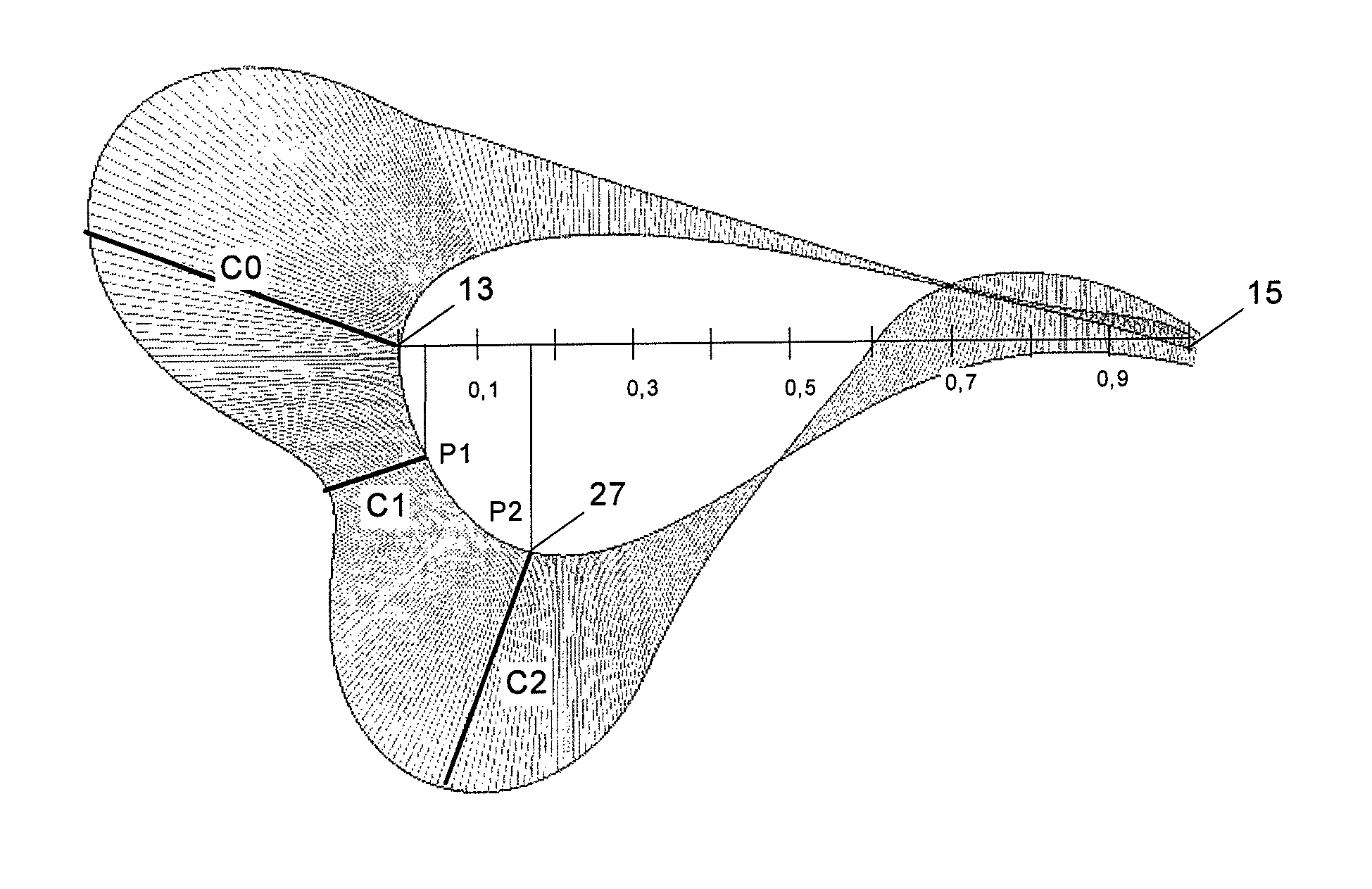
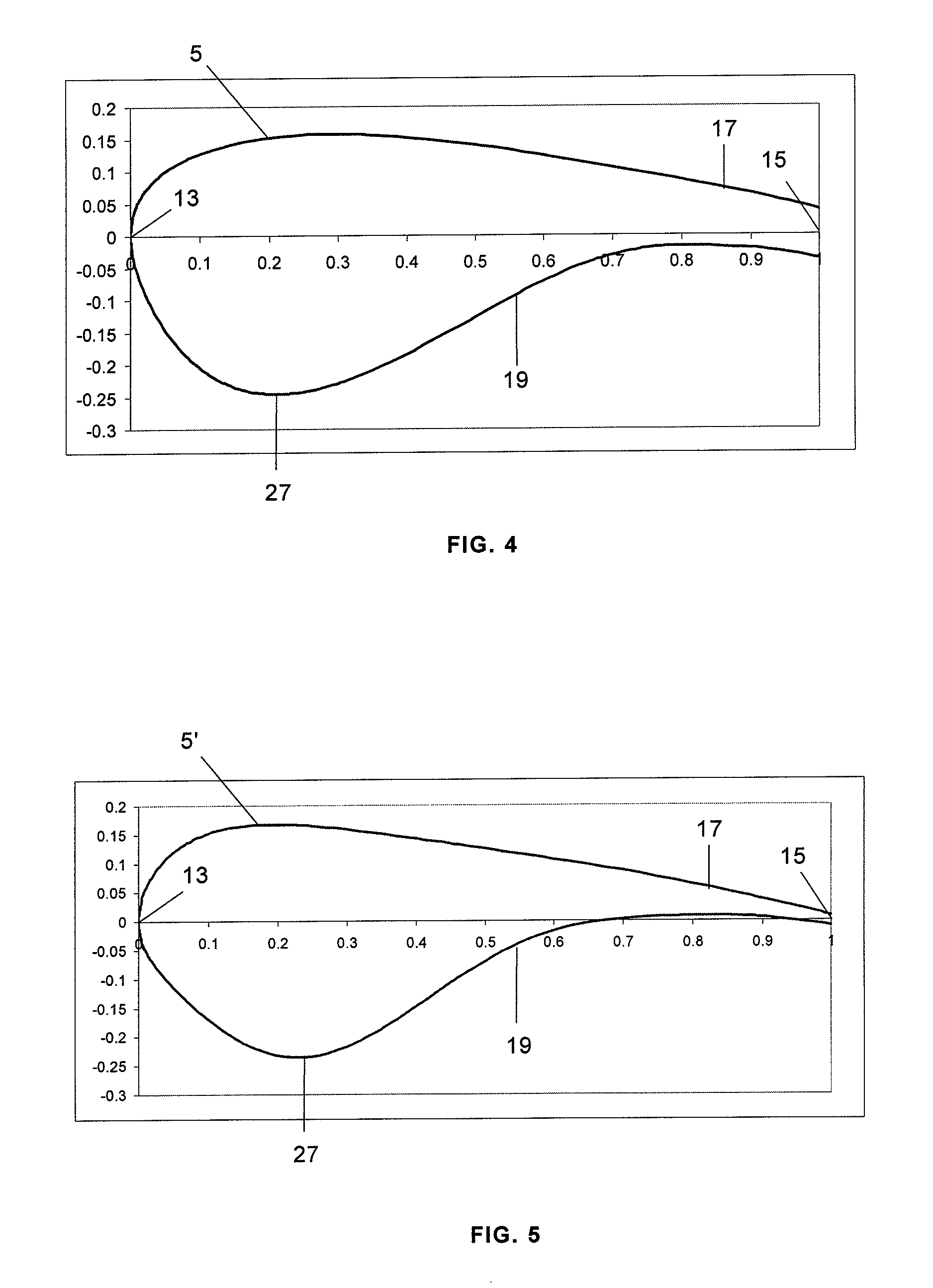
The invention relates to an aerodynamic profile for the root of a wind turbine blade having a double leading edge, including a leading edge (13), a trailing edge (15) and suction and pressure sides (17, 19) between the leading edge (13) and the trailing edge (15). The profile (5, 5′, 5′) has a relative thickness in the 30%-50% range in at least one section (37) of the root region (31). In addition, the convex portion (21) of the pressure side (19) is configured such that the curvature thereof decreases from a value C0 at the leading edge (13) to a value C1 at a first point P1 and subsequently increases to a value C2 at a second point P2, after which it decreases to a value 0 at the end of the convex portion (21).

Description

FIELD OF THE INVENTION[0001]The invention relates to an aerodynamically optimised wind turbine blade and in particular to an optimised wind turbine blade in the root region.BACKGROUND[0002]The airfoils or profiles used in wind turbine blades have different performance characteristics in the root region, the mid-span region and the tip region.[0003]Wind turbine blades have generally in the root region profiles of higher relative thickness than in the rest of the blade. An example of a root region profile having a relative thickness in the range 24%-26% is disclosed in EP 0 663 527 A1.[0004]A profile in the root region of the blade is desired to have a high maximum lift coefficient and a high lift-to-drag ratio close to the maximum lift coefficient to aid rotor start-up and energy production at medium wind speeds. However, the value of the lift coefficient is usually moderate in this type of profiles and occurs at moderate low angles of attack. These effects result on the necessity of...

Claims


Application Information

Patent Timeline
Patent Type & Authority Patents(United States)
IPC IPC(8): B63H1/26
CPCF03D1/0641F05B2240/301F05B2250/70F05D2240/121F05D2240/303Y02E10/721F05B2250/711Y02E10/72F03D1/0608
Inventor NAGY, GIDEONROMERO SANZ, IGNACIOJIMENEZ DE LAGO, MARIO
Owner GAMESA INNOVATION & TECH SA
Learn More