
Medical imaging apparatus, medical image processing apparatus, ultrasonic imaging apparatus, ultrasonic image processing apparatus and method of processing medical images

a technology of medical imaging and ultrasonic imaging, applied in image enhancement, instruments, angiography, etc., can solve the problems of difficult estimation of motion vector, easy deviation of tracking contours in cardiac phase e′, and inability to track errors, etc., to achieve simple operation and improve accuracy

Active Publication Date: 2013-09-03
TOSHIBA MEDICAL SYST CORP
View PDF7 Cites 2 Cited by
  • Summary
  • Abstract
  • Description
  • Claims
  • Application Information

AI Technical Summary

Benefits of technology

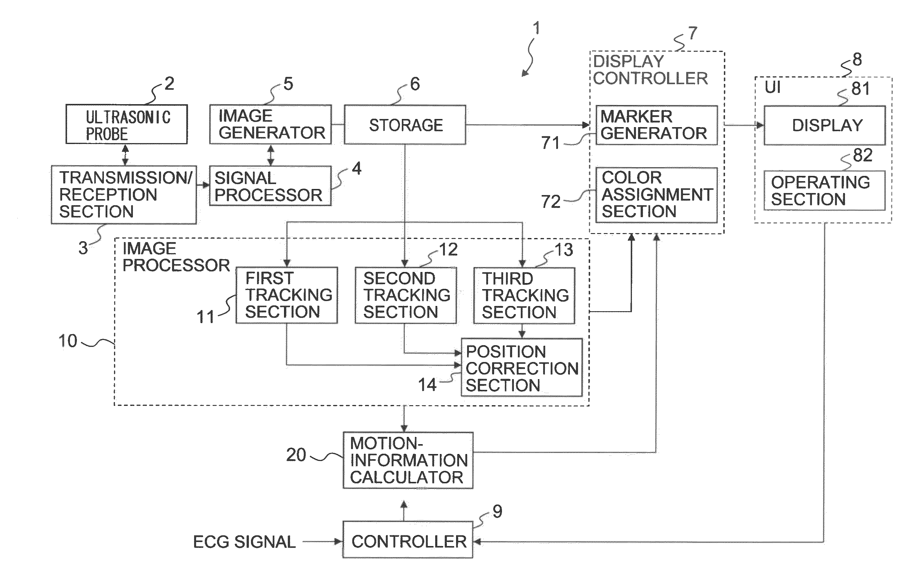
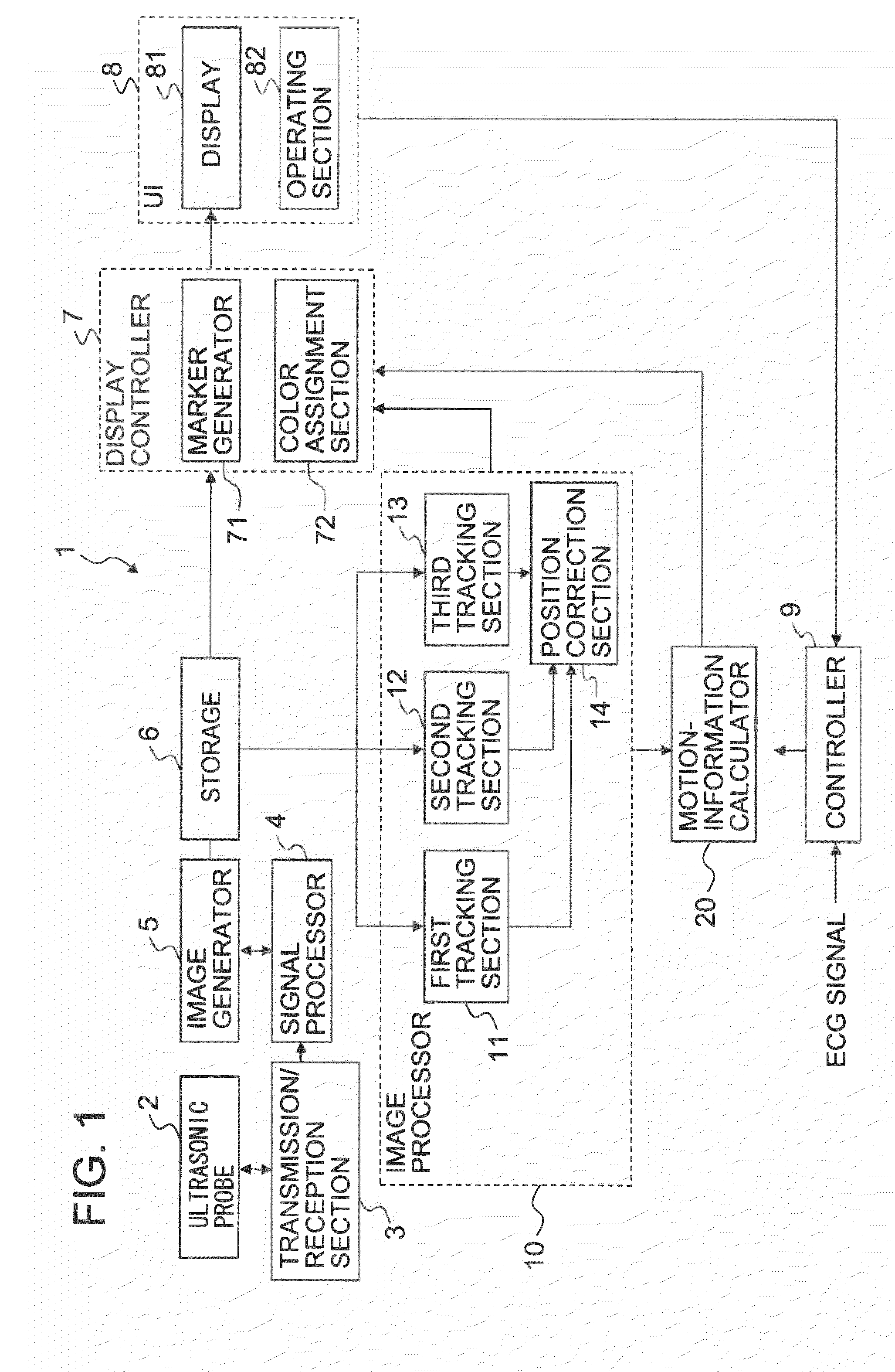
[0010]The purpose of this invention is to provide a medical imaging apparatus, a medical image processing apparatus, an ultrasonic imaging apparatus, an ultrasonic image processing apparatus and a method of processing medical images in which, during processes of tracking a region of interest, deviations from the tracking position are unlikely to occur from when tracking is started, and even when there is a deviation in the tracking position, the tissue movement included in the region of interest may be evaluated more accurately by correcting the tracking position through simple operations.
[0013]This allows deviations in the tracking performed by the tracking part to become less likely. Moreover, even if there is a deviation in the tracking performed by the tracking part, the movement of the tissue may be obtained more accurately by correcting the tracking position through a simple operation.

Problems solved by technology

In the tracking process based on the ST method, it is difficult to estimate the motion vector during diastole (especially early diastole phase E′), when the movement speed of the heart is fastest, and tracking of the contours in cardiac phase E′ deviates easily.
However, tracking errors may occur not only during diastole but also during systole (cardiac phase S′, in which the motion is relatively slow).
Sequential corrections of tracking errors occurring during systole or diastole using only the above tracking method (ReTrack2 function) in order to obtain more accurate evaluation results are troublesome and inconvenient.

Method used


Image

  • Medical imaging apparatus, medical image processing apparatus, ultrasonic imaging apparatus, ultrasonic image processing apparatus and method of processing medical images
  • Medical imaging apparatus, medical image processing apparatus, ultrasonic imaging apparatus, ultrasonic image processing apparatus and method of processing medical images
  • Medical imaging apparatus, medical image processing apparatus, ultrasonic imaging apparatus, ultrasonic image processing apparatus and method of processing medical images

Examples


modified example 1

[0128]In the first illustrative embodiment described above, the operator specifies the initial contour twice. Consequently, compared to existing technology, the operational procedure increases by one step and the operations may become troublesome. Therefore, the operational procedure performed by the operator may be reduced by automatically detecting and setting the position of the initial contour.

(Step S10)

[0129]First, the operator uses the operating section 82 to specify one heartbeat (cardiac phase t=end diastole ED0 to the following end diastole ED1). When the one heartbeat is specified, information indicating the specified cardiac phase (end diastole ED0 to the following end diastole ED1) is output from the user interface (UI) 8 to the image processor 10 and the display controller 7.

(Step S11)

[0130]The image processor 10 acquires cross-sectional image data of the first initial time phase T1 (end diastole ED0) from the storage 6 and detects the first initial contour IC1 of the e...

modified example 2

[0142]In the first illustrative embodiment and Modified Example 1 described above, cases in which initial contours are set in the two time phases of the end diastole ED and the end systole ES have been described. In Modified Example 2, as in existing technology, considering the fact that tracking errors tend to occur during diastole (especially after cardiac phase E′). ST processing is executed after preliminarily setting an initial contour in a third cardiac phase after cardiac phase E′. This preliminarily restrains the tracking results not only during systole but also during diastole, allowing for further improvements in the tracking accuracy of the first ST process.

[0143]Furthermore, in Modified Example 2, due to the need to set 3 initial contours, the number of steps for setting the initial contours increases by 1 step. However, due to the decrease in cases requiring a correction step during diastole using the retracking process (ReTrack2 function), the overall operational proce...


PUM


Abstract

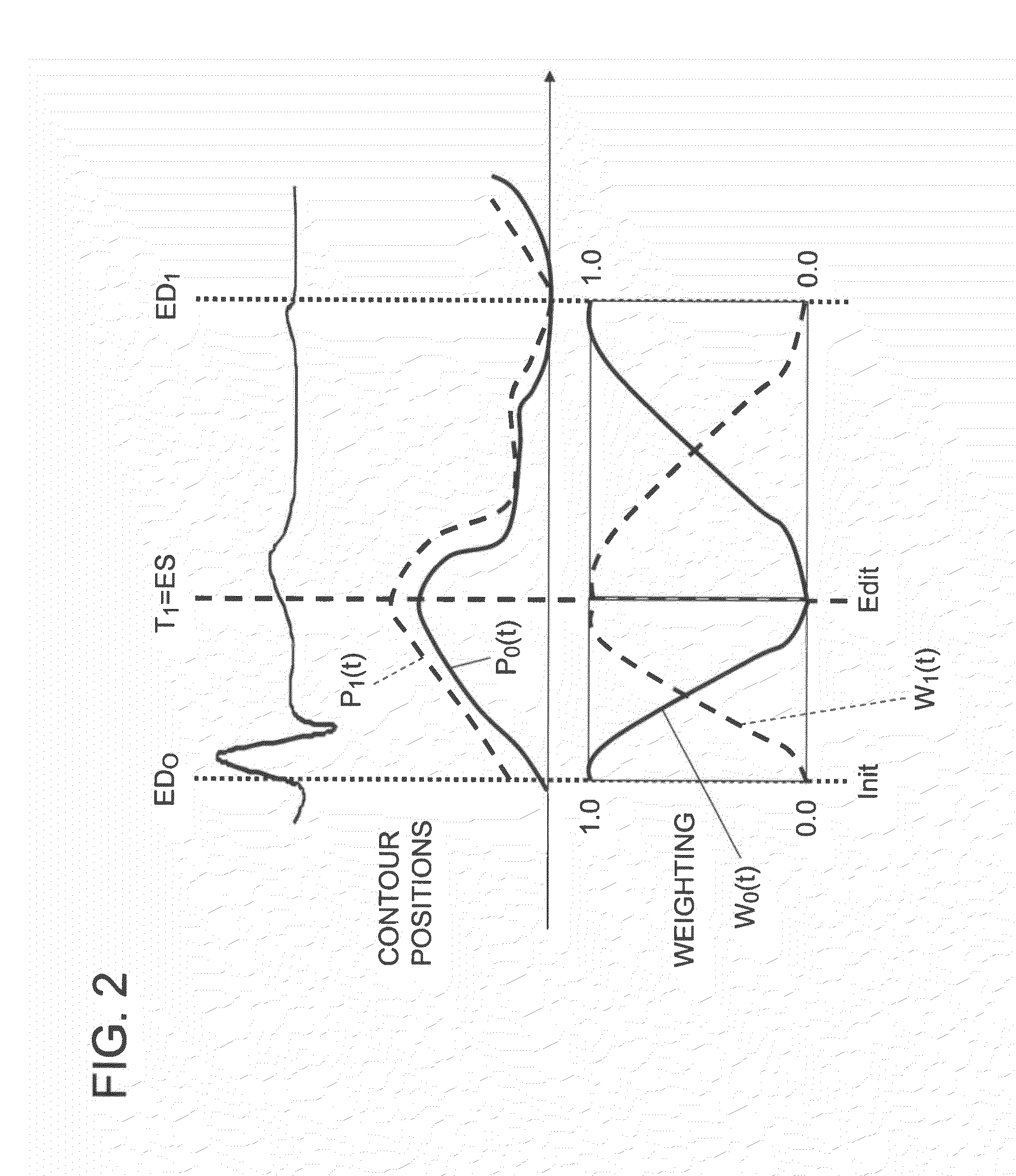
Based on medical image data acquired in each time phase included in a one-cycle interval, first tracking part tracks the position of a first region of interest set in a first time phase in each time phase and tracks the position of a second region of interest set in a second time phase in each time phase. Based on position information of the first region of interest and the second region of interest in each time phase, position correction part obtains position information of a region of interest in each time phase so that it passes through the position of the first region of interest in the first time phase and the position of the second region of interest in the second time phase. Motion-information calculator obtains motion information of a tissue based on the obtained position information.

Description

BACKGROUND OF THE INVENTION[0001]1. Field of the Invention[0002]This invention relates to a medical imaging apparatus and an ultrasonic imaging apparatus that acquire medical images representing a subject and uses those medical images to obtain the state of motion of the subject. The invention also relates to both a medical image processing apparatus and an ultrasonic image processing apparatus that obtain the state of motion of a subject by using medical images as well as a method of processing medical images.[0003]2. Description of the Related Art[0004]Objective and quantitative functional evaluations of living tissue such as the myocardium are extremely important for diagnosing the living tissue. For example, methods for acquiring image data of a heart using an ultrasonic imaging apparatus to conduct quantitative evaluations based on the image data have been proposed.[0005]As one example, technology (hereinafter referred to as “speckle tracking”, or “ST”) for calculating local wa...

Claims


Application Information

Patent Timeline
Patent Type & Authority Patents(United States)
IPC IPC(8): G06K9/00
CPCA61B8/08A61B8/483G06T7/0097G06T7/2033A61B5/055A61B6/03A61B6/503A61B6/504A61B8/485G06T2207/10132G06T2207/30048A61B8/0891G06T7/174G06T7/246
Inventor ABE, YASUHIKOKAWAGISHI, TETSUYA
Owner TOSHIBA MEDICAL SYST CORP
Learn More