MIMO channel state information estimation with coupled iterative two-stage ranking

a technology of state information estimation and mimo channel, applied in pulse technique, site diversity, baseband system details, etc., can solve the problems of high computational complexity and computational complexity of csi estimation techniques mentioned above, and achieve the reduction of the number of required reference symbols or feedback samples, improve estimation accuracy, and reduce the complexity of algorithms

Active Publication Date: 2013-09-10
TELEFON AB LM ERICSSON (PUBL)
View PDF11 Cites 8 Cited by
  • Summary
  • Abstract
  • Description
  • Claims
  • Application Information

AI Technical Summary

Benefits of technology

[0007]Some embodiments described herein impose knowledge of the time domain tap delay channel model structure across multiple input / output antenna pairs to improve estimation accuracy and / or reduce the number of required reference symbols or feedback samples. In one embodiment, identical tap delay positions are enforced for all antenna pairs that share close spatial vicinity.
[0008]Some embodiments disclosed herein implement iterative ranking and simple least square estimation instead of convex optimization. A first ranking function imposes the channel structure knowledge and a second ranking function directs the iterative algorithm toward the sparse solutions from the corresponding convex optimization. A goodness of fit function controls the structural quality for different application scenarios. Parameters in the ranking and goodness of fit functions allow the same iterative algorithm to be deployed in systems with different interference characteristics, different types of estimation quality requirements and different levels of MIMO model uncertainty. The complexity of the algorithm can be reduced by employing simple least square estimation sub-steps and is further controllable by appropriately setting the maximum number of iterations and the amount of least goodness improvement. High estimation quality is provided with a computation complexity reduction factor of more than ten.

Problems solved by technology

However, the approaches mentioned above are suboptimal for MIMO-based systems because the physical specifics of the MIMO setup are not used in the estimation process either to reach the best accuracy or to reduce the amount of feedback samples.
In addition, the CSI estimation techniques mentioned above are computationally complex.
For example, a very effective technique for estimating the time domain tap delay model is based on convex optimization, which incurs high computational complexity, particularly for MIMO-based systems due to the multitude of transmit / receive antenna pairs.

Method used


Image

  • MIMO channel state information estimation with coupled iterative two-stage ranking
  • MIMO channel state information estimation with coupled iterative two-stage ranking
  • MIMO channel state information estimation with coupled iterative two-stage ranking

Examples


Embodiment Construction

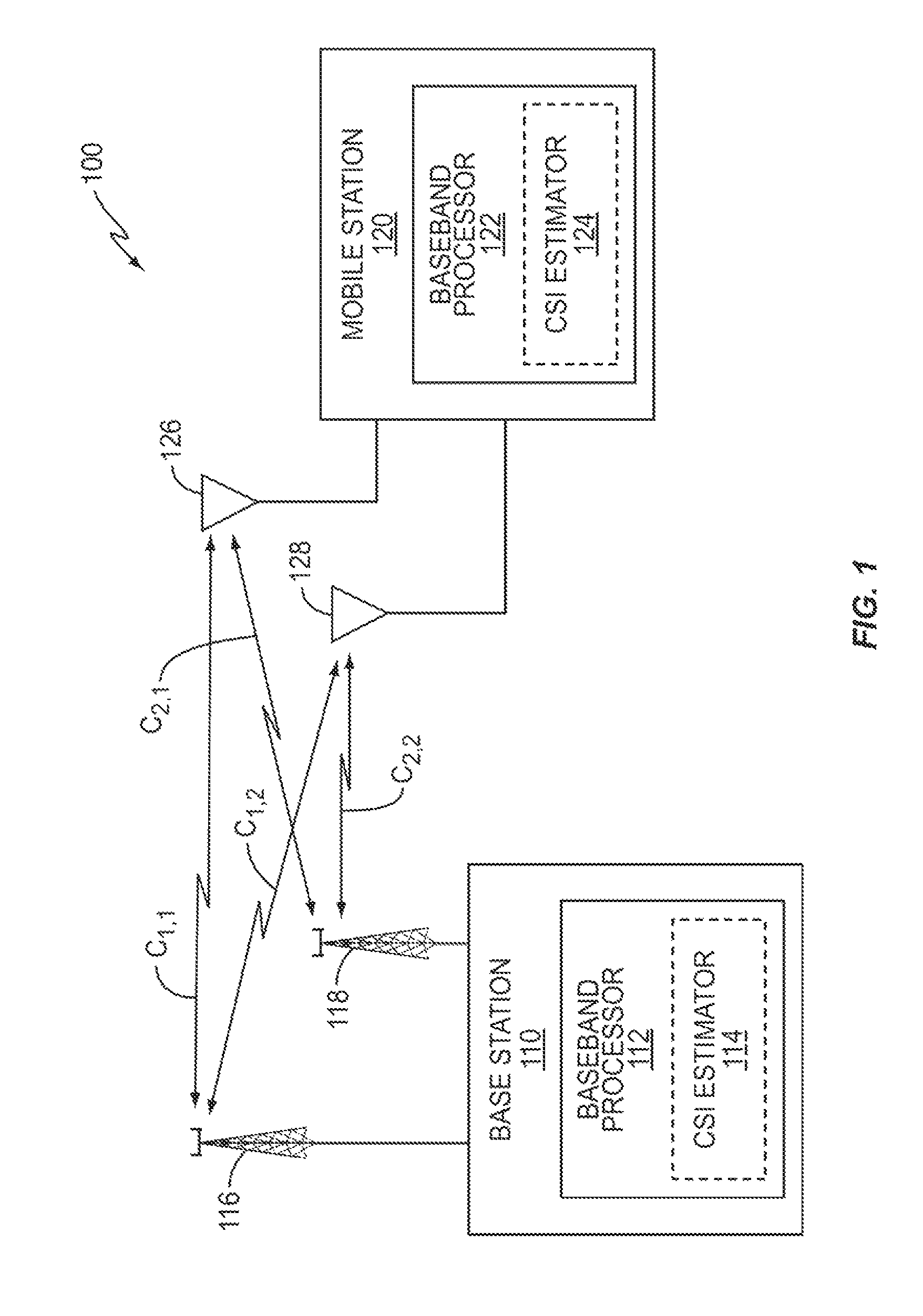
[0015]FIG. 1 illustrates an embodiment of a wireless communication network 100 including a base station 110 serving a mobile station 120 such as a UE. The base station 110 transmits communication signals in the downlink over radio frequency channels to the mobile station 120. The mobile station 120 can transmit signals in the uplink to the base station 110. In both cases, the received signal may be characterized as the transmitted signal, altered by channel effects, plus noise and interference. At least one of the base station 110 and / or the mobile station 120 has more than one antenna. In the downlink direction, the mobile station 120 is the wireless receiver and the base station 110 is the wireless transmitter. The opposite holds true in the uplink direction, i.e. the base station 110 is the receiver and the mobile station 120 is the transmitter. Thus, the term ‘receiver’ as used herein can mean either the base station 110 or the mobile station 120 depending on the communication l...


PUM


Abstract

A plurality of wireless channels link a transmitter and a receiver, each channel corresponding to a different transmit-receive antenna pair. Channel state information is estimated for the plurality of wireless channels by grouping the plurality of channels into one or more groups, each group including the channels associated with two or more collocated transmit and/or receive antennas. A set of delay tap values is iteratively estimated in the time domain for each group of channels so that the channels included in the same group are associated with the same delay tap values. A frequency domain channel response of each of the channels included in the same group of channels is estimated based on the set of delay tap values estimated for the group.

Description

TECHNICAL FIELD[0001]The present invention relates generally to wireless communications, and particularly to an efficient system and method of estimating, at a wireless receiver, multiple-input and / or multiple-output (MIMO) channel state information (CSI) from sparse data transmitted by a wireless transmitter.BACKGROUND[0002]Wireless communication networks transmit communication signals in the downlink over radio frequency channels from fixed transceivers, known as base stations, to mobile user equipment (UE) within a geographic area normally referred to as a cell. Similarly, the UE can transmit signals in the uplink to one or more of the base stations. In both cases, the received signal may be characterized as the transmitted signal, altered by channel effects, plus noise and interference.[0003]To recover the transmitted signal from a received signal, a receiver must estimate both the channel and the noise / interference. The characterization of a channel is typically referred to as ...

Claims


Application Information

Patent Timeline
Patent Type & Authority Patents(United States)
IPC IPC(8): H04B7/02
CPCH04B7/024H04L25/0218H04W24/02H04L25/0232H04B7/0413H04L25/022
Inventor CHENG, JUNG-FU
Owner TELEFON AB LM ERICSSON (PUBL)
Why Eureka
Try Eureka