Total knee prosthesis

Active Publication Date: 2013-09-24
BERCOVY MICHEL +2
View PDF14 Cites 8 Cited by
  • Summary
  • Abstract
  • Description
  • Claims
  • Application Information

AI Technical Summary

Benefits of technology

[0035]According to another advantageous feature, the ovoid contact surfaces of the glenoid cavities of the insert are connected, at each flexure level, through a concave isthmian surface both forwards and backwards and inscribed in the hyperbolic paraboloid defined by the interglenoidal connecting surface. This allows transmission of the stresses into the central portion of the prosthesis, but also axial rotation about a vertical axi

Problems solved by technology

This prosthesis configuration does not allow the prosthetic knee to adapt to all the movements since it imposes a constant posterior displacement; further the flexion-extension movements of the joint are movements constrained by the co-operation of the cam and of the abutment, therefore unidirectional and identical move

Method used


Image

  • Total knee prosthesis
  • Total knee prosthesis
  • Total knee prosthesis

Examples


Embodiment Construction

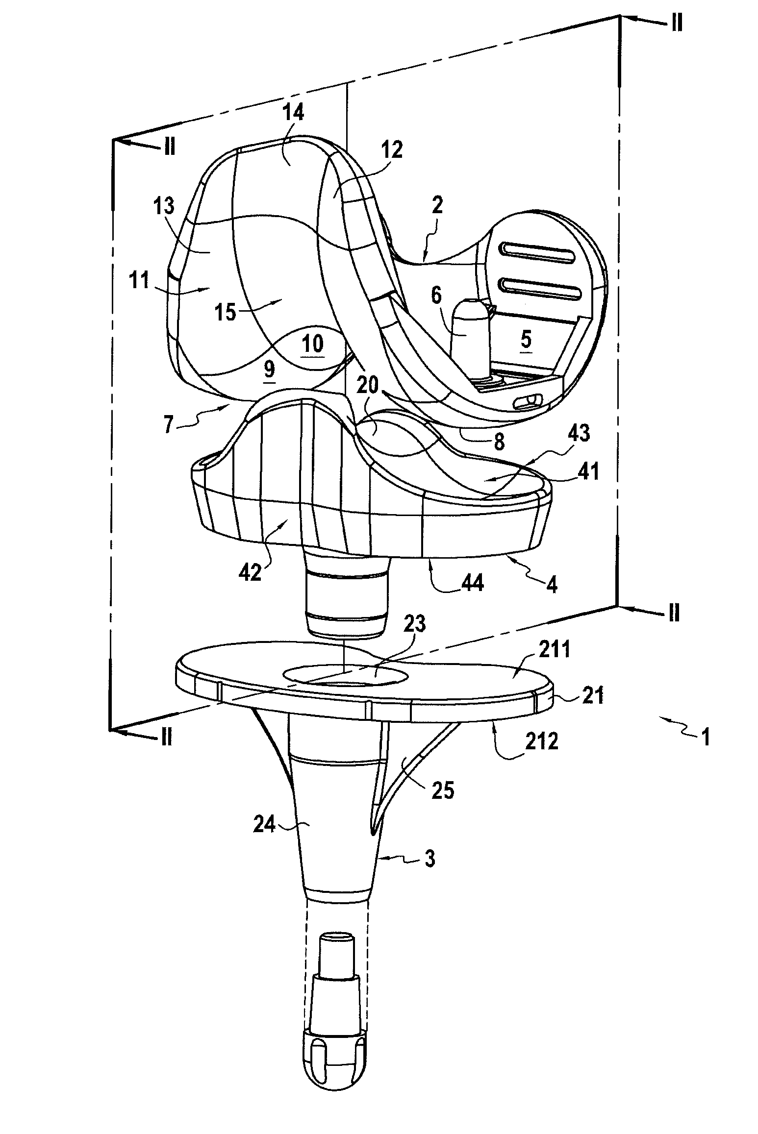
[0049]As this is apparent from the figures, the object of the invention relates to a total prosthesis 1 of the knee conventionally comprising a femoral implant 2 and a tibial implant 3, both preferably consisting of a biocompatible stainless metal alloy, and an articular insert 4, generally in a plastic material such as polyethylene. However, one or more elements of this prosthesis may also consist of alumina ceramic or of alumina and zirconia ceramic or biocompatible resins for example.

[0050]The femoral implant 2 and the tibial implant 3 are both intended to be adapted after resection, onto the femoral low epiphysis and the tibial upper epiphysis, respectively.

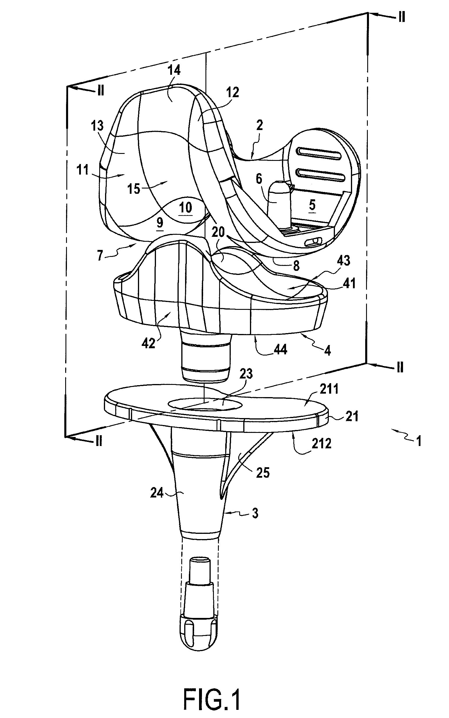
[0051]The femoral implant 2 seen from the side as partly illustrated in FIG. 2 has a substantially non-symmetrical U-shape between the branches of which a housing 5 is delimited for attachment onto the lower epiphysis of the femur, in particular by fitting two protruding lugs 6 into each other.

[0052]The femoral implant 2 also...


PUM


Abstract

The present invention relates to a total knee prosthesis. This prosthesis includes a femoral implant (2) including two condyles (8, 9) delimiting between them an intercondylar notch (10), a tibial implant (3) intended to rest on the end of the tibia, and an articular insert (4) interposed between the tibial implant and the femoral implant and the upper surface of which (41) includes two glenoid cavities (18, 19) with an external profile (181, 191) congruent with the external profile (81, 91) of the condyles (7, 8) of the femoral implant and connected together through an interglenoidal connecting surface (20). According to the invention, the intercondylar notch (10) and the interglenoidal connecting surface (20) have congruent contact surfaces (101, 201) which are inscribed in two mating hyperbolic paraboloids and the contact surface (181, 191) of the glenoid cavities (18, 19) have in a horizontal section an ovoid shape and its inclined point (P) is located posteriorly to the line of larger width (L) of the insert.

Description

FIELD OF THE INVENTION[0001]The present invention relates to the field of joint prostheses, and more particularly in this particular field, to a novel total knee prosthesis.BACKGROUND ART[0002]Prostheses for the joint of the knee have to be designed in order to observe two main rules:[0003]a tribological rule: they have to undergo minimum wear during use;[0004]a kinematic rule: the operation of the prosthesis should be as comfortable as possible for the patient in all daily activities.[0005]And above all, tribology should meet kinematics and conversely kinematics should be compliant with tribology. It is within the scope of this dual converse obligation that the present invention is located.[0006]In this field of knee prostheses, many prior proposals of total knee prosthesis have already been made. These total prostheses traditionally include three functional elements: a femoral element intended to be implanted on the lower end of the femur, a tibial element adapted so as to be impl...

Claims


Application Information

Patent Timeline
IPC IPC(8): A61F2/38
CPCA61F2/3868A61F2002/30934A61F2002/30952A61F2310/00179A61F2310/00203A61F2310/00239
Inventor BERCOVY, MICHELKERBOULL, LUCBRACY, DAVID
Owner BERCOVY MICHEL
Why Eureka
Try Eureka