Motor controller and electronic power steering apparatus
a technology of electronic power steering apparatus and motor controller, which is applied in the direction of electric generator control, dynamo-electric converter control, dynamo-electric gear control, etc., can solve the problems of large voltage to be applied to the brushless motor, power supply voltage restriction, etc., to reduce the motor torque in the high revolution range, avoid the damage caused by the motor controller, and reduce the effect of the motor torqu
- Summary
- Abstract
- Description
- Claims
- Application Information
AI Technical Summary
Benefits of technology
Problems solved by technology
Method used
Image
Examples
first embodiment
2. First Embodiment
2.1 Overall Configuration of Motor Control Unit
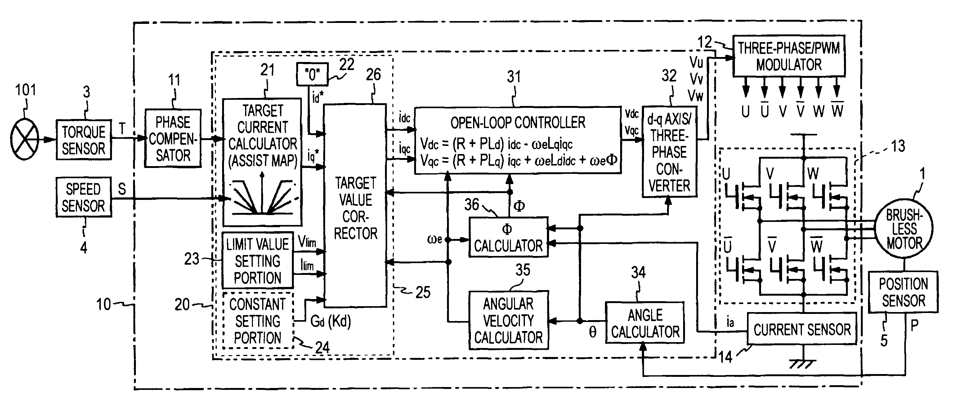
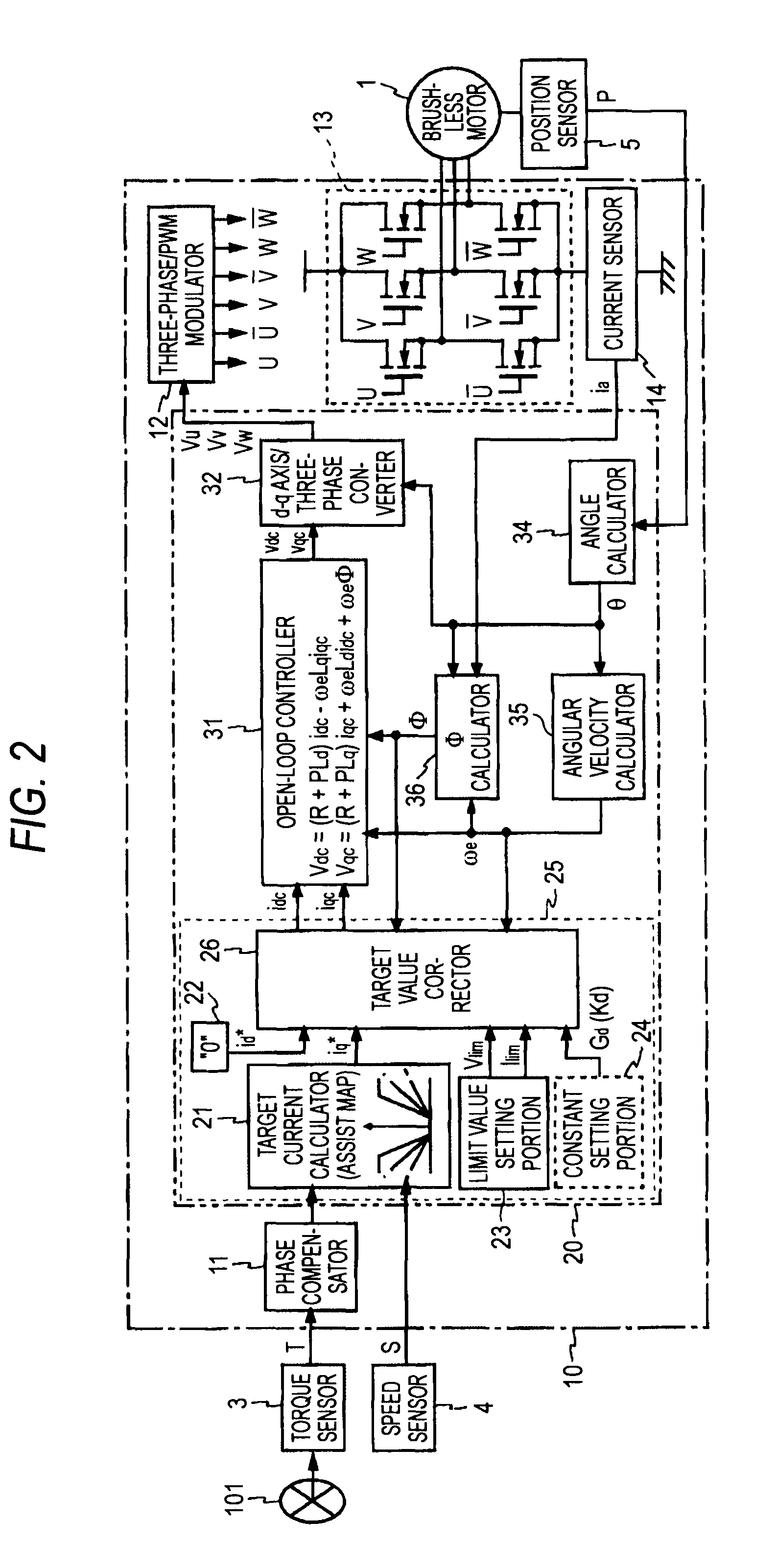
[0057]FIG. 2 is a block diagram showing a configuration of the motor controller according to a first embodiment of the present invention. The motor controller shown in FIG. 2 is constructed by using the ECU 10, and drives the brushless motor 1 with three-phase windings (not shown) in u-phase, v-phase, and w-phase. The ECU 10 is equipped with a phase compensator 11, a microcomputer 20, a three-phase / PWM (Pulse Width Modulation) modulator 12, a motor driving circuit 13, and a current sensor 14.
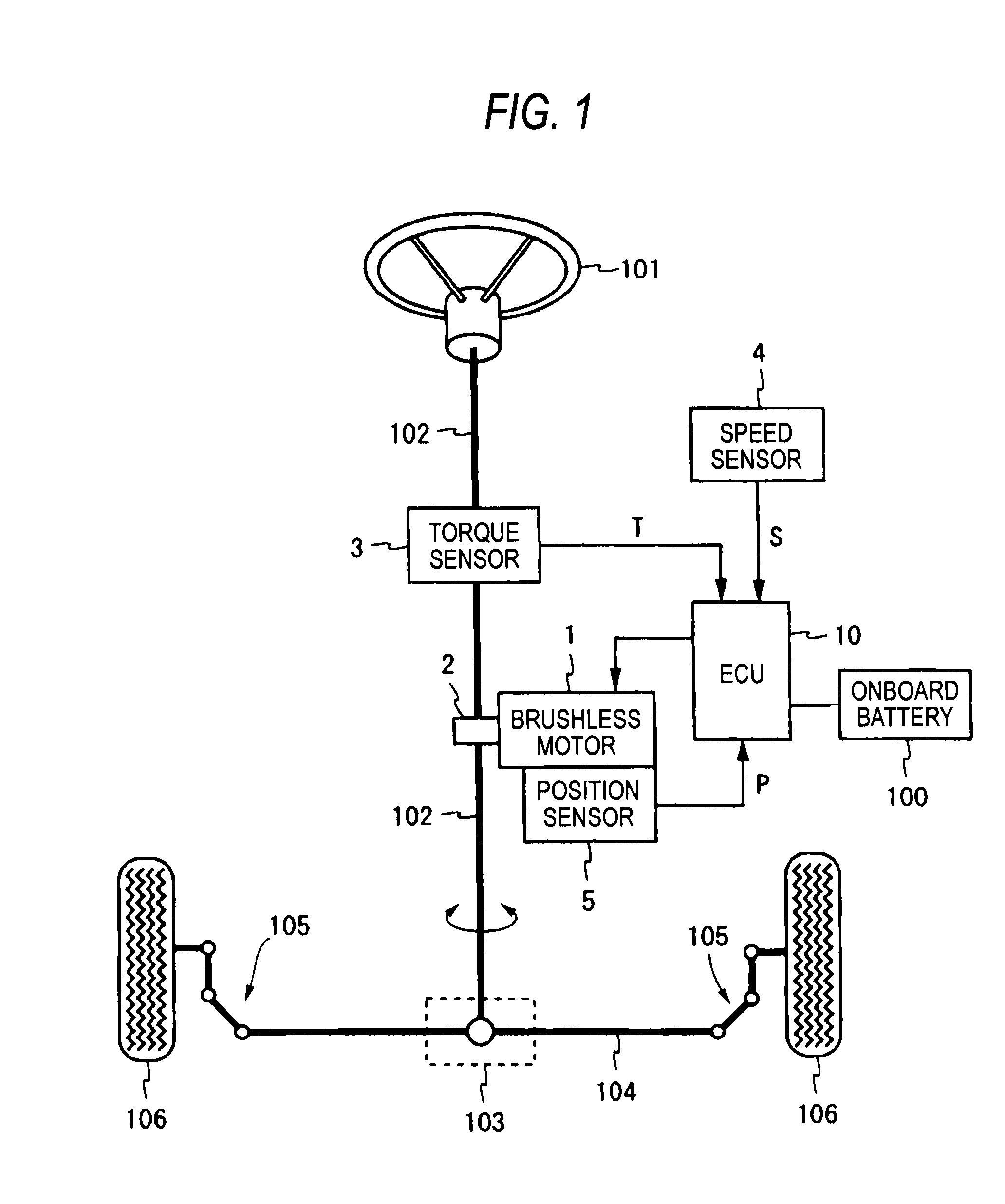
[0058]The steering torque T output from the torque sensor 3, the vehicle speed S output from the speed sensor 4, and the turning position P output from the position sensor 5 are input into the ECU 10. The phase compensator 11 applies a position compensation to the steering torque T. The microcomputer 20 functions as a controlling section for detecting a voltage command value used to drive the brushless motor 1. Details of function...
second embodiment
3. Second Embodiment
[0125]Next, the motor controller according to a second embodiment of the present invention will be explained hereunder. A basic configuration of the motor controller according to the present embodiment is similar to the first embodiment and is given as shown in FIG. 2, and the same reference symbols are affixed to the same or corresponding portions. In the following, mainly a difference from the first embodiment will be explained hereunder.
[0126]In the present embodiment, the target value correcting process that the microcomputer 20 executes to implement the target value correcting portion 26 is different from the first embodiment. FIG. 10 is a flowchart showing a target value correcting process that the microcomputer 20 executes to implement the target value corrector 26 in the present embodiment. An operation of the target value corrector 26 according to the present configurative example will be explained with reference to FIG. 10 hereunder. Here, the process a...
PUM
 Abstract
Description
Claims
Application Information
 - R&D
- Intellectual Property
- Life Sciences
- Materials
- Tech Scout
- Unparalleled Data Quality
- Higher Quality Content
- 60% Fewer Hallucinations
Browse by: Latest US Patents, China's latest patents, Technical Efficacy Thesaurus, Application Domain, Technology Topic, Popular Technical Reports.
© 2025 PatSnap. All rights reserved.Legal|Privacy policy|Modern Slavery Act Transparency Statement|Sitemap|About US| Contact US: help@patsnap.com


