

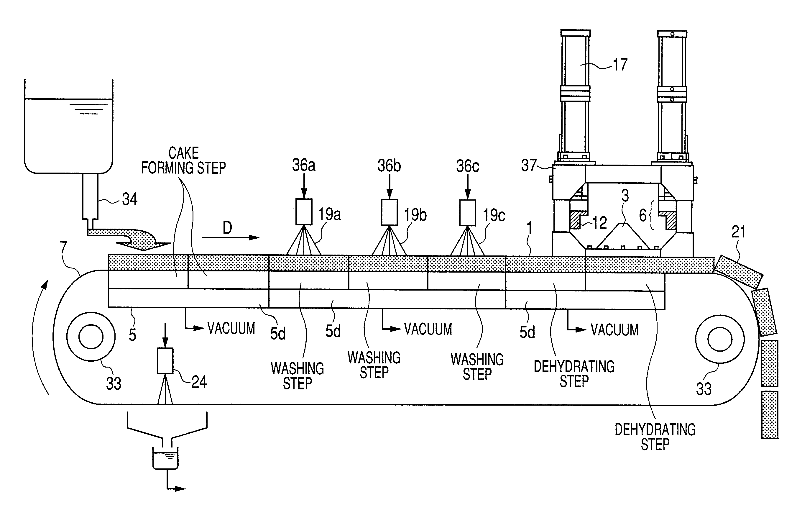
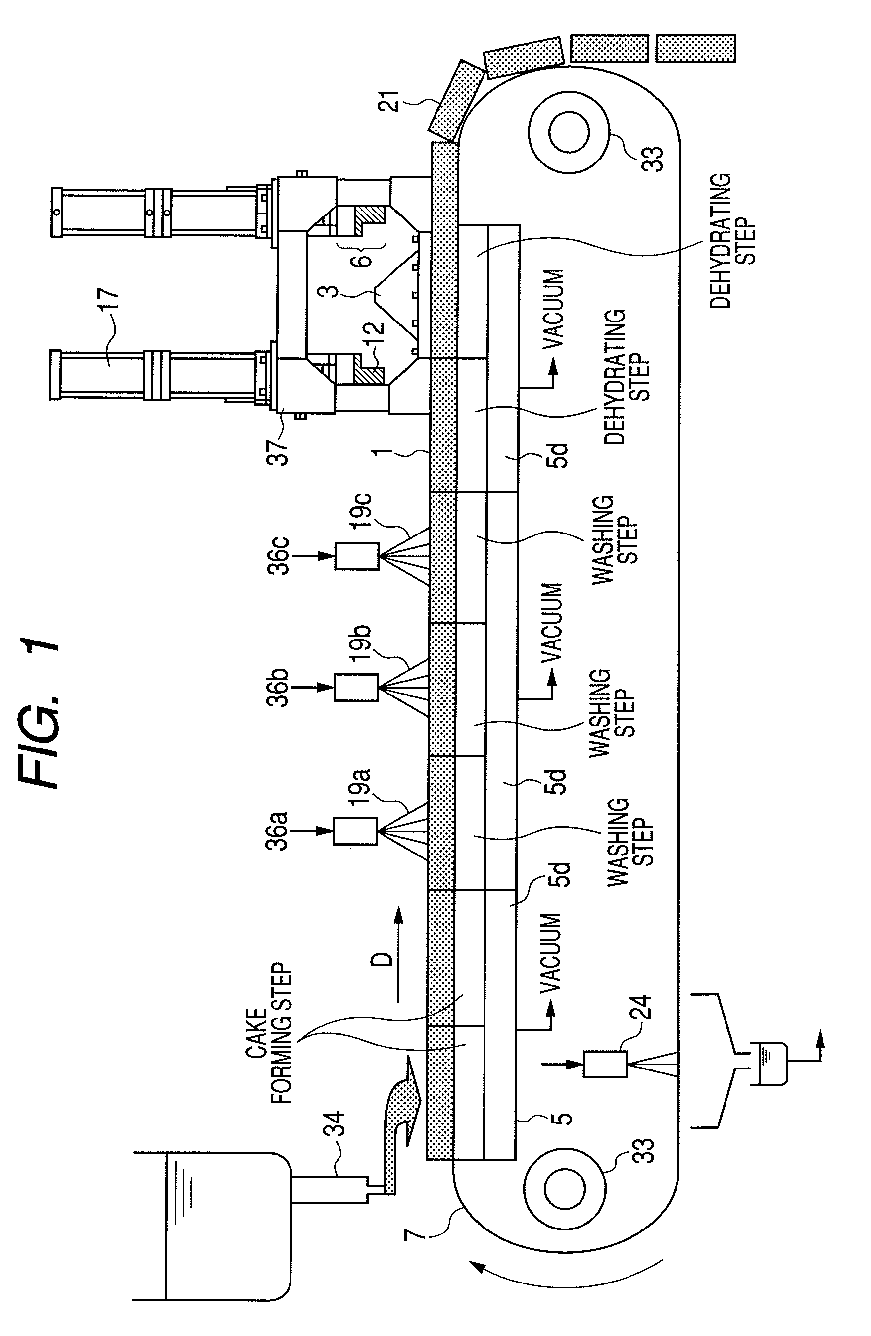
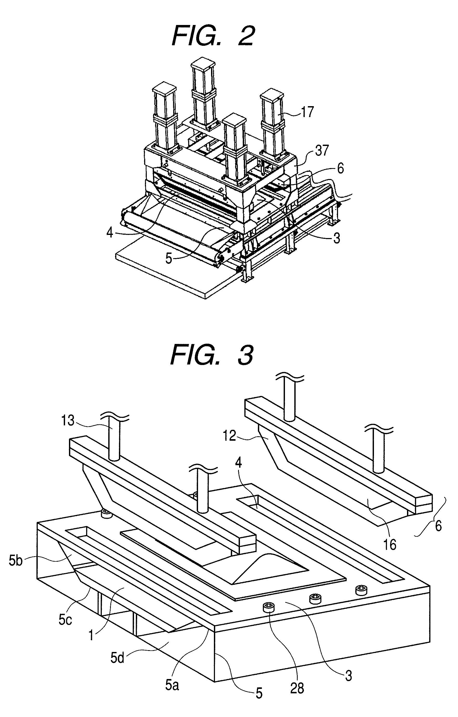
Filter cloth traveling type belt filter and production method of toner particles
a technology of toner particles and filter cloth, which is applied in the direction of filtration separation, separation processes, instruments, etc., can solve the problems of increasing the load in the drying step, deteriorating dehydration ability, and increasing the load of the drying step, so as to achieve the effect of efficiently sealing the aeration air and sufficiently reducing the water content of the wet toner particle cak
- Summary
- Abstract
- Description
- Claims
- Application Information
AI Technical Summary
Benefits of technology
Problems solved by technology
Method used
Image

Examples
example 1
[0190]710 parts by mass of ion-exchange water and 850 parts by mass of 0.1 mol / liter Na3PO4 aqueous solution were added, and maintained at 60° C. with stirring at 4800 rpm using Clearmix (manufactured by M Technique). Thereto, 68 parts by mass of 1.0 mol / liter—CaCl2 aqueous solution was gradually added to prepare an aqueous dispersive medium containing a minute water-insoluble dispersion stabilizing agent Ca3 (PO4)2.
[0191]A formulation including
124.0 parts by mass of styrene monomer,
36.0 parts by mass of N-butylacrylate,
13.0 parts by mass of copper phthalocyanine pigment,
40.0 parts by mass of the above-mentioned styrene resin,
10.0 parts by mass of a polyester resin
(Terephthalic acid—propylene oxide modified bispenol A (2 mol adduct)—ethylene oxide modified bispenol A (2 mol adduct) (molar ratio 51:30:20); Acid value 9, glass transition temperature 60° C., Mw=10,000, Mw / Mn=3.20),
0.8 parts by mass of E-88 (manufactured by Orient Chemical Industries, Ltd.), and
15.0 parts by mass of HNP...
example 2
[0224]The dehydrated toner particle cake prepared as in Example 1 was subjected to the dehydration and washing and drying treatments under the same manner as in Example 1 except that the distance K between the lower surface of the gas discharging part and the top surface of horizontal level area of the tray was changed to 400 mm to prepare toner particles. The thickness of the sealing member before compression at the point of time when the dehydration and washing treatment was carried out for consecutive 3 hours was 60.0 mm and the compressibility of the sealing member at the time of the compression was 75%. This dehydrated toner particle cake after the dehydration and washing treatment for 3 hours was disintegrated and the water content was measured and found to be 23%. At the point of time when consecutive 100-hour dehydration and washing treatment was carried out, the thickness of the sealing member before compression was distorted to 42.9 mm. Therefore, the compressibility was 6...
example 3
[0225]The dehydrated toner particle cake prepared as in Example 1 was subjected to the dehydration and washing and drying treatments under the same manner as in Example 1 except that the distance K between the lower surface of the gas discharging part and the top surface of horizontal level area of the tray was changed to 15 mm to prepare toner particles. The thickness of the sealing member before compression at the point of time when the dehydration and washing treatment was performed for consecutive 3 hours was 60.0 mm and the compressibility of the sealing member at the time of the compression was 75%. The dehydrated toner particle cake after this dehydration and washing treatment for 3 hours was disintegrated and the water content was measured and found to be 21%. At the point of time when the consecutive 100-hour dehydration and washing treatment was carried out, the thickness of the sealing member before compression was distorted to 42.9 mm. Therefore, the compressibility was ...
PUM
| Property | Measurement | Unit |
|---|---|---|
| thickness | aaaaa | aaaaa |
| thickness | aaaaa | aaaaa |
| water content | aaaaa | aaaaa |
Abstract
Description
Claims
Application Information