Micromechanical housing comprising at least two cavities having different internal pressure and/or different gas compositions and method for the production thereof

a micromechanical housing and internal pressure technology, applied in the direction of microstructural devices, microstructural technology, gyroscopes/turn-sensitive devices, etc., can solve the problems of small gaps between metal pellets, prolonging the reliable function and life of the sensor

Active Publication Date: 2013-10-01
FRAUNHOFER GESELLSCHAFT ZUR FOERDERUNG DER ANGEWANDTEN FORSCHUNG EV
View PDF17 Cites 37 Cited by
  • Summary
  • Abstract
  • Description
  • Claims
  • Application Information

AI Technical Summary

Problems solved by technology

The housing of micro-sensors is one of the least developed yet one of the most important and most challenging technology fields within the art of microsystem technology.
A hermetically sealed encapsulation protects micro-sensors against harmful environmental agents (dust, mechanical and chemical damages) and prolongs the reliable function and life of the sensor.
With these methods, the sintering of metal particles is barely initiated so that small gaps remain between the metal pellets.

Method used


Image

  • Micromechanical housing comprising at least two cavities having different internal pressure and/or different gas compositions and method for the production thereof
  • Micromechanical housing comprising at least two cavities having different internal pressure and/or different gas compositions and method for the production thereof
  • Micromechanical housing comprising at least two cavities having different internal pressure and/or different gas compositions and method for the production thereof

Examples


example a

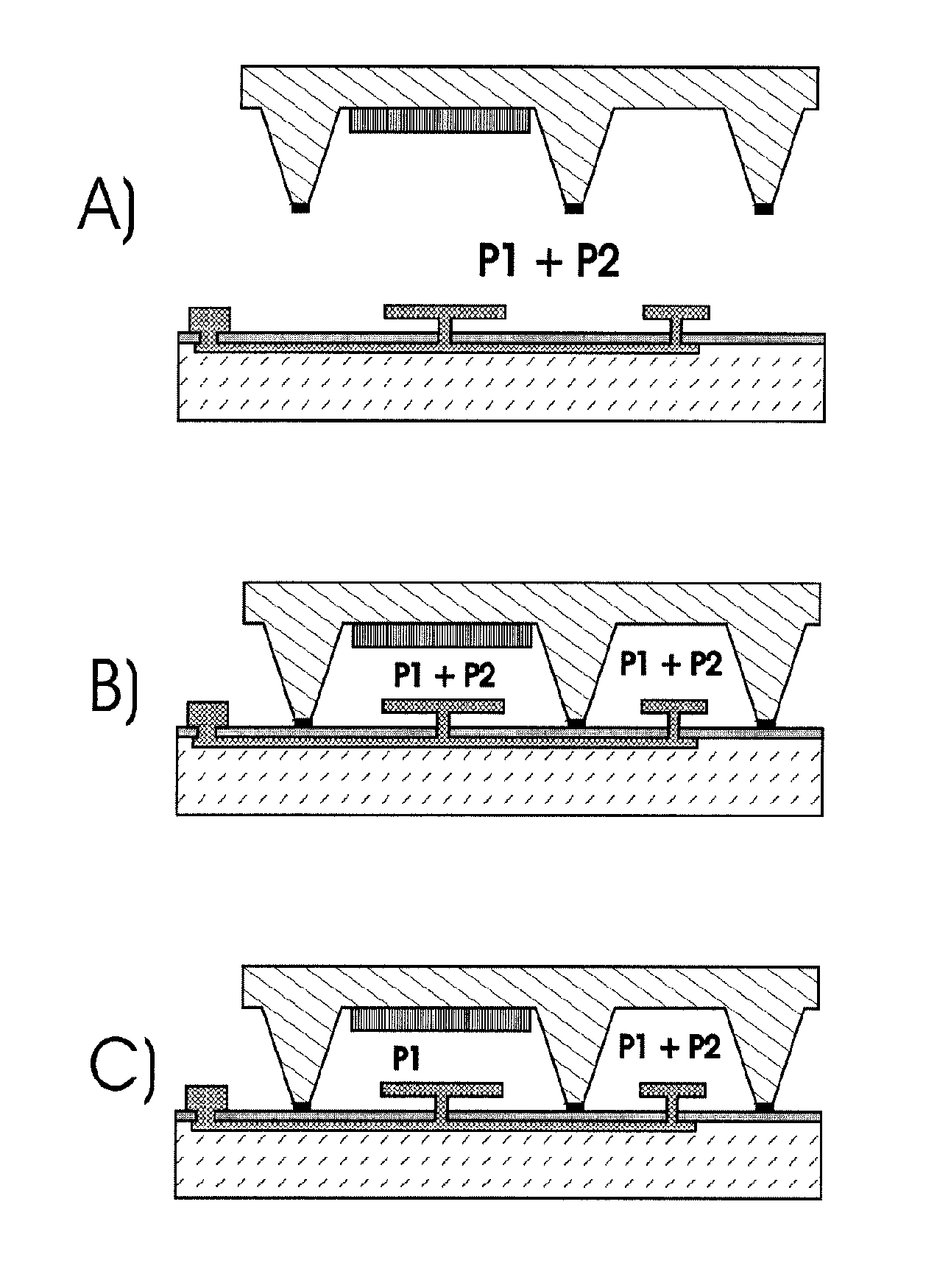
[0043]The bonding chamber is primed with pure gas of type A (e.g., Nitrogen) at pressure P1.

[0044]

Chamber with Getter:Chamber without GetterBefore Getter activationNitrogen with partial pressure P1Nitrogen with partial pressure P1P = P1P = P1After Getter activationNitrogen is bound to GetterTheoretical cavity pressureP = 0P = P1Effectively achievable cavityP = 1E−6 barP = P1 + / − 1E−3 mbarpressure(Remaining pressure caused bycontamination)

example b

[0045]The bonding chamber is primed with a gas mixture consisting of gas of type A (e.g., Nitrogen) at partial pressure P1, and gas of type B (e.g., Argon) at partial pressure P2.

[0046]

Chamber with Getter:Chamber without GetterBefore Getter activationNitrogen with partial pressure P1Nitrogen with partial pressure P1Argon with partial pressure P2Argon with partial pressure P2P = P1 + P2P = P1 + P2After Getter activationNitrogen is bound to Getter ArgonNitrogen with partial pressure P1remainsArgon with partial pressure P2Theoretical cavity pressureP = P2P = P1 + P2Effectively achievable cavityP = P2 + / − 1E−6 barP = P1 + P2 + / − 1E−6 mbarpressure

[0047]In this example, consider a production gas at 4 mbar N2 and 0.2 mbar Ar. In the chamber with Getter, there will be a total pressure after getter activation of 0.2 mbar, in the chamber without Getter the pressure will be 4.2 mbar.

[0048]In both cases, consideration has to be given to gas which enters the cavity through contamination, surface...


PUM


Abstract

The present application relates to a multiple component which is to be subsequently individualized by forming components containing active structures, in addition to a corresponding component which can be used in microsystem technology systems. The multiple component and / or component comprises a flat substrate and also a flat cap structure which are bound to each other such that they surround at least one first and one second cavity per component, which are sealed against each other and towards the outside. The first of the two cavities is provided with getter material and due to the getter material has a different internal pressure and / or a different gas composition than the second cavity. The present application also relates to a method for producing the type of component and / or components for which gas mixtures of various types of gas have a different absorption ratio in relation to the getter material.

Description

BACKGROUND OF THE INVENTION[0001]1. Field of the Invention[0002]This invention relates to a method for the combined and preferably wafer-based housing of micromechanical systems comprising individually different operating pressures. Using a single operation, this method enables to selectively fill one cavity 1 with defined gas pressure P1 and one cavity 2 with gas pressure P2, in which P1 and P2 can be chosen independently. This method allows to combine different micromechanical systems into one component. The degree of integration of these systems is therefore increased substantially. In addition, this invention relates to micromechanical systems comprising at least two cavities and different internal pressures and / or different gas compositions in each cavity.[0003]2. Description of Related Art[0004]For quite some time, components produced by microsystem technology (micro electro-mechanical systems, MEMS) have allowed the miniaturized and cost-effective production of sensors and ac...

Claims


Application Information

Patent Timeline
Patent Type & Authority Patents(United States)
IPC IPC(8): H01L23/20H01L27/14
CPCB81B7/0038B81C1/00285B81B7/02G01C19/5783B81B7/00B81C1/00
Inventor MERZ, PETERREINERT, WOLFGANGOLDSEN, MARTENSCHWARZELBACH, OLIVER
Owner FRAUNHOFER GESELLSCHAFT ZUR FOERDERUNG DER ANGEWANDTEN FORSCHUNG EV
Why Eureka
Try Eureka