Interactive control system for an HVAC system

Active Publication Date: 2013-10-08
COPELAND COMFORT CONTROL LP
View PDF7 Cites 103 Cited by
  • Summary
  • Abstract
  • Description
  • Claims
  • Application Information

AI Technical Summary

Problems solved by technology

Thus, the various HVAC component controllers rely on the master controller to communicate operating instructions and system diagnostics, and each controller does not independently manage its operation based on diagnostic information transmitted by other subordinate HVAC controllers.

Method used


Image

  • Interactive control system for an HVAC system
  • Interactive control system for an HVAC system
  • Interactive control system for an HVAC system

Examples


first embodiment

[0021]One first embodiment of an interactive controller 24 is shown in FIG. 3. The interactive outdoor air conditioning compressor unit controller 24 may comprise a processor 60 and a plurality of switching means 62, 64 for controlling the switching of line voltage 66, 68 to the compressor motor 42 and the condenser fan motor. The switching means preferably comprise relays such as a A22500P2 relay manufactured by American Zettler. The condenser fan motor relay 62 and at least one compressor motor relay 64 are also in connection with the processor 60. The processor 60 may be a 28 pin PIC16F microprocessor manufactured by Microchip. Relays 62 and 64 have first and second contacts, at least one of which may be in communication with the processor 60, and preferably at least the non-moving contact of which is in communication with the processor. The processor 60 is able to activate the relay and sense voltage at the stationary contact to verify when the contacts are closed and open. Thus...

second embodiment

[0034]In an interactive controller, an indoor air handler / circulator blower controller 28 is provided that comprises a processor 100 and at least one output signal 102 which will request the blower motor controller 38 to operate at a low speed corresponding to “Y1” first stage cooling operation or at a high speed corresponding to “Y2” second stage cooling operation. The indoor air handler / blower controller 28 includes a low voltage power supply that is preferably a half wave regulated power supply (not shown) comprising a diode in series with a transistor and a regulating capacitor and zener diode for gating the transistor. The power supply may also be a small transformer and zener diode circuit. The low voltage power supply powers the processor 100, which includes a plurality of Analog to Digital data inputs for receiving information from various data inputs in connection with the indoor blower controller 28. An example of such an indoor blower controller 28 is a 49B Series Control...

fourth embodiment

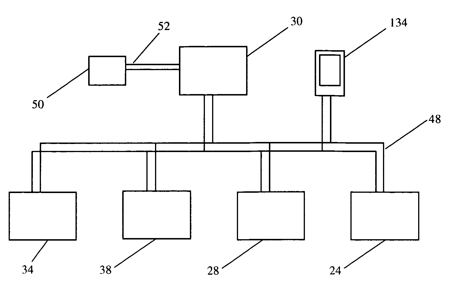
[0062]a plurality of interactive controllers that form a system is shown in FIG. 4. The system comprises an integrated furnace controller 442, for controlling the operation of one or more components of the heating system. The integrate furnace controller 442 is capable of modifying the operation of the one or more heating system components it controls, such as a two-stage gas valve, in response to receiving information transmitted via the two-wire “bus” network about the operation of another controller or component within the heating, ventilation, and air conditioning system. The controller for a circulating air blower 428 may, for example, include a variable speed circulator blower motor controller 438 with an inverter driver, which if overheated would reduce the speed of the circulator blower. The blower controller could responsively communicate its reduced speed information by transmitting a signal via the two-wire “bus” network lines. The signal may be intended for a specific co...


PUM


Abstract

An interactive system for controlling the operation of an HVAC system is provide that comprises a thermostat for initiating the operation of the HVAC system in either a full capacity mode of operation or at least one reduced capacity mode of operation, and a controller for an outside condenser unit having a condenser fan motor and a compressor motor, the controller being capable of operating the compressor in a full capacity mode and at least one reduced capacity mode. The system also comprises a controller for an indoor blower unit having a blower fan motor, the controller being capable of operating the blower fan motor in a full capacity mode an at least one reduced capacity mode. The system further includes a communication means for transmitting information between the outside condenser unit controller and at least the indoor blower controller, where the information relates to the operation of the indoor blower and the outdoor condenser unit. The indoor blower controller responsively controls the operation of the blower fan motor in a full capacity mode or a reduced capacity mode based on the information received from the outdoor unit controller, and the outdoor unit controller responsively controls the operation of the compressor in a full capacity mode or a reduced capacity mode based on the information received from the indoor blower controller.

Description

CROSS REFERENCE TO RELATED APPLICATIONS[0001]This application is a continuation-in-part of commonly assigned, U.S. patent application Ser. No. 11 / 063,806 filed Feb. 23, 2005 now U.S. Pat. No. 7,296,426, which is hereby incorporated herein by reference.FIELD OF THE INVENTION[0002]The present invention relates to controllers for interactively controlling an HVAC system, and more particularly to an integrated system of individual controllers for interactively controlling various components in the HVAC system.BACKGROUND OF THE INVENTION[0003]Many present HVAC systems employ a plurality of controllers for communicating information within a master / slave network, in which a “master” thermostat or similar central controller is the master that coordinates communication between the various slave components within the HVAC system. Such networks require various subordinate controllers to be configured for communication with and control by a master thermostat or communication controller, without...

Claims


Application Information

Patent Timeline
Patent Type & Authority Patents(United States)
IPC IPC(8): F23N1/00
CPCF24F11/0009F24F11/0086F25B49/02G05D23/1904F24F2011/0067F24F2011/0091F25B2600/025F25B2600/111F25B2700/151F25B2700/2104F25B2700/2106F25B2700/21152Y02B30/743F24F11/30F24F11/54F24F11/52Y02B30/70F24F11/65F24F11/63
Inventor BUTLER, WILLIAM P.GAROZZO, JAMES P.
Owner COPELAND COMFORT CONTROL LP
Why Eureka
Try Eureka