Method for reducing dielectric constant of film using direct plasma of hydrogen

a technology of dielectric constant and direct plasma, which is applied in the field of reducing the dielectric constant of films, can solve the problems of increasing electricity consumption, increasing the degree of film shrinkage, and unable to maintain the mechanical strength of films, so as to achieve low dielectric constant and maintain mechanical strength.

Active Publication Date: 2013-10-08
ASM JAPAN
View PDF9 Cites 379 Cited by
  • Summary
  • Abstract
  • Description
  • Claims
  • Application Information

AI Technical Summary

Benefits of technology

[0009]Some embodiments provides a technology for forming interlayer insulating films for multilayer wiring, particularly, a method of forming low dielectric constant films which maintain mechanical strength and achieve low dielectric constant without changing other film properties.

Problems solved by technology

As a result, such fine wiring causes signal delay, and increases electricity consumption.
However, even though the size of one molecule of porogen is small, if the amount of the porogen is large, the molecules of porogen are likely to be close to each other and cause aggregation.
With this pore, not only can the mechanical strength of the film no longer be maintained, but also it causes obstacles in the process of producing semiconductor manufacturing equipment, because some substances such as gas, metal molecules, and liquid chemicals can easily penetrate into the pore.
However, by doing so, it also causes a greater degree of film shrinkage, which results in producing films with higher dielectric constant.

Method used


Image

  • Method for reducing dielectric constant of film using direct plasma of hydrogen
  • Method for reducing dielectric constant of film using direct plasma of hydrogen
  • Method for reducing dielectric constant of film using direct plasma of hydrogen

Examples


example 1

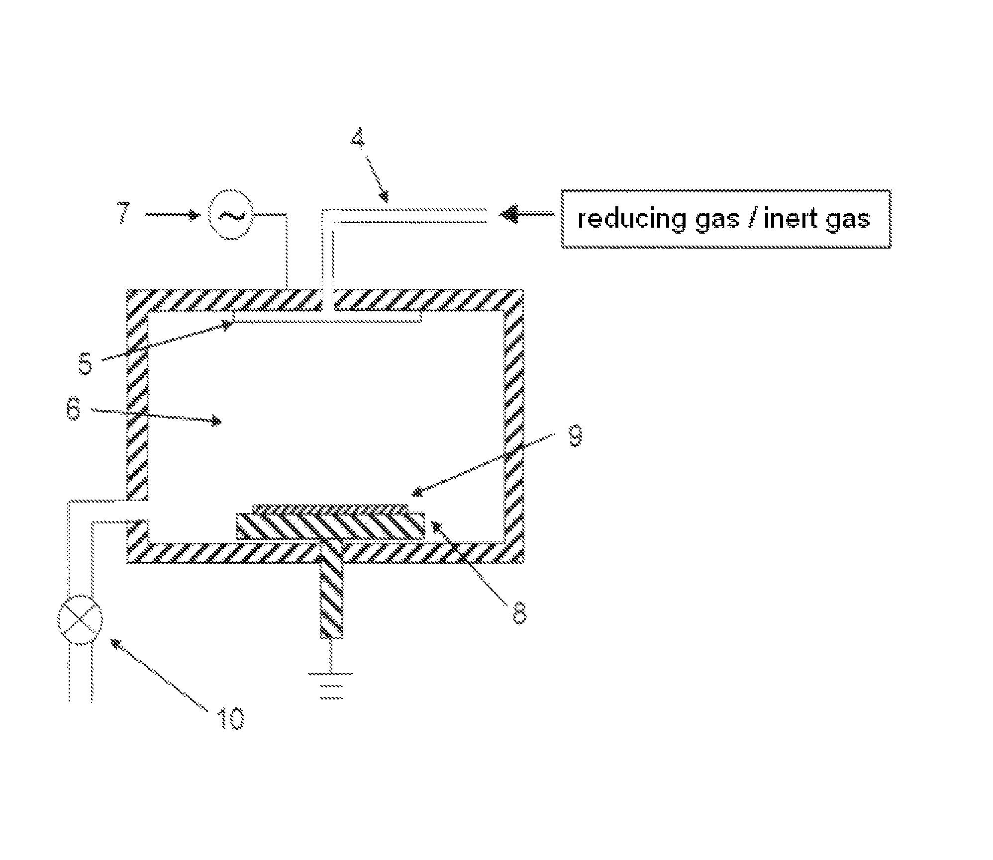
[0051]Using a reaction chamber for plasma enhanced CVD illustrated in FIG. 1, a film having a thickness of 250 nm was deposited on a 300-mm wafer under the following conditions:

[0052]Temperature: 250° C.;

[0053]Pressure: 800 Pa;

[0054]He: 900 sccm;

[0055]O2: 25 sccm;

[0056]DEMS: 53.4 sccm to 126.8 sccm;

[0057]ATPR: 236.8 sccm to 309.1 sccm;

[0058]HRF: 1,000 W;

[0059]Distance between the showerhead and the susceptor: 8 mm.

[0060]UV-curing was conducted in a UV radiation chamber for 5 minutes at 400° C. under a pressure of 665 Pa while introducing N2 at 4,000 sccm, using a UV power of 100 W / cm.

[0061]Direct plasma treatment was conducted for 10 minutes in the same reaction chamber as film deposition, after the UV-curing, under the following conditions:

[0062]Temperature of Substrate: 250° C.;

[0063]Pressure: 40 Pa;

[0064]Hydrogen Gas Flow: 300 sccm;

[0065]RF Power (13.56 MHz): 400 W;

[0066]Distance between the showerhead and the susceptor: 8 mm.

[0067]As a comparative example, the same processes as ...

example 2

[0068]Using an apparatus for plasma enhanced CVD illustrated in FIG. 1, a film having a thickness of 250 nm was deposited on a 200-mm wafer under the following conditions:

[0069]Temperature: 250° C.;

[0070]Pressure: 800 Pa;

[0071]He: 900 sccm;

[0072]O2: 25 sccm;

[0073]DEMS: 105.1 sccm;

[0074]ATPR: 263.1 sccm;

[0075]HRF: 1,000 W;

[0076]Distance between the showerhead and the susceptor: 8 mm.

[0077]UV-curing was conducted in a UV radiation chamber for 5 minutes at 400° C. under a pressure of 665 Pa while introducing N2 at 4,000 sccm, using a UV power of 100 W / cm.

[0078]Direct plasma treatment was conducted for 10 minutes in the same reaction chamber as film deposition, after the UV-curing, under the following conditions:

[0079]Temperature of Substrate: 250° C.;

[0080]Pressure: 30 Pa;

[0081]Hydrogen Gas Flow: 100 sccm;

[0082]RF Power (13.56 MHz): 100 W;

[0083]Distance between the showerhead and the susceptor: 11 mm.

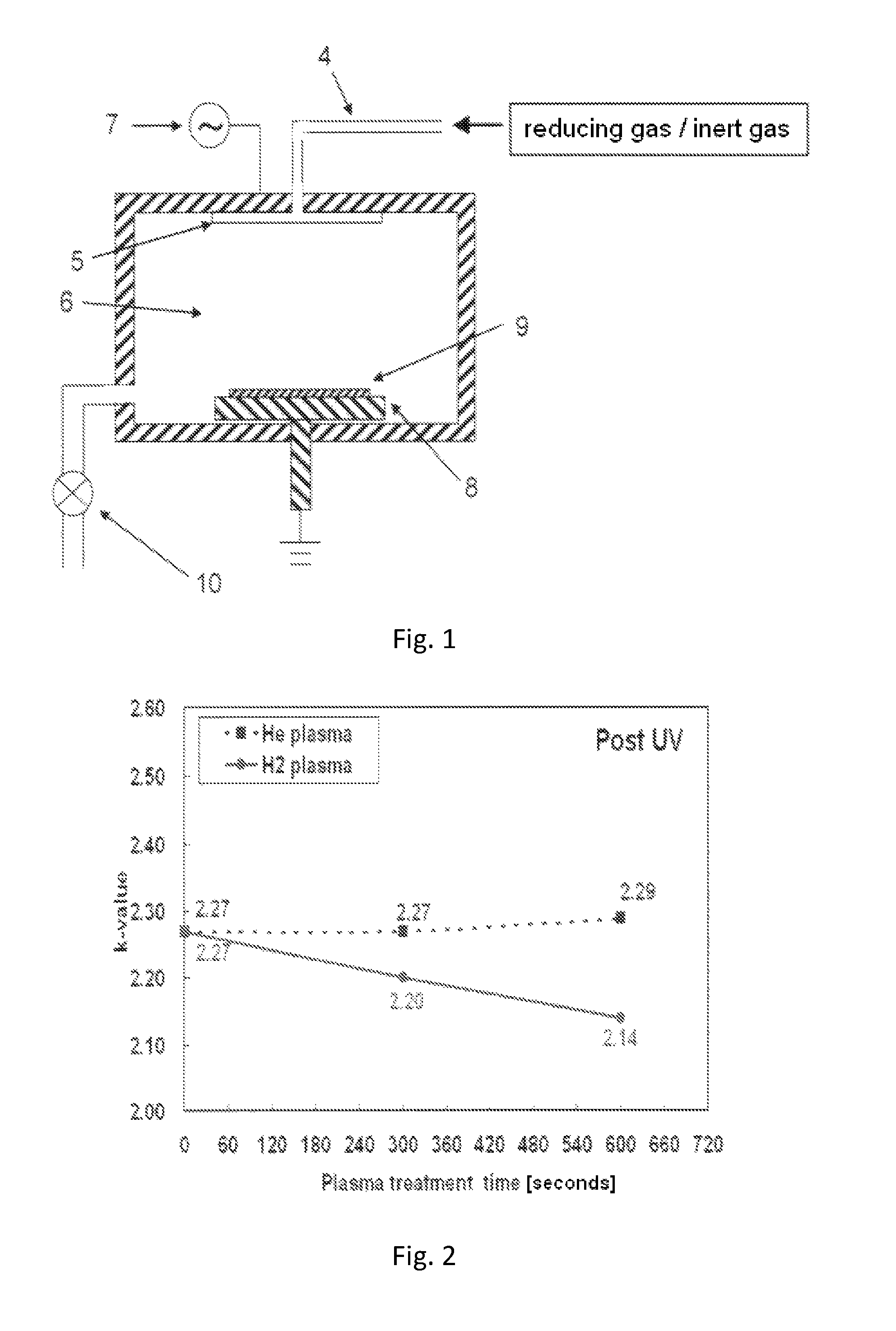
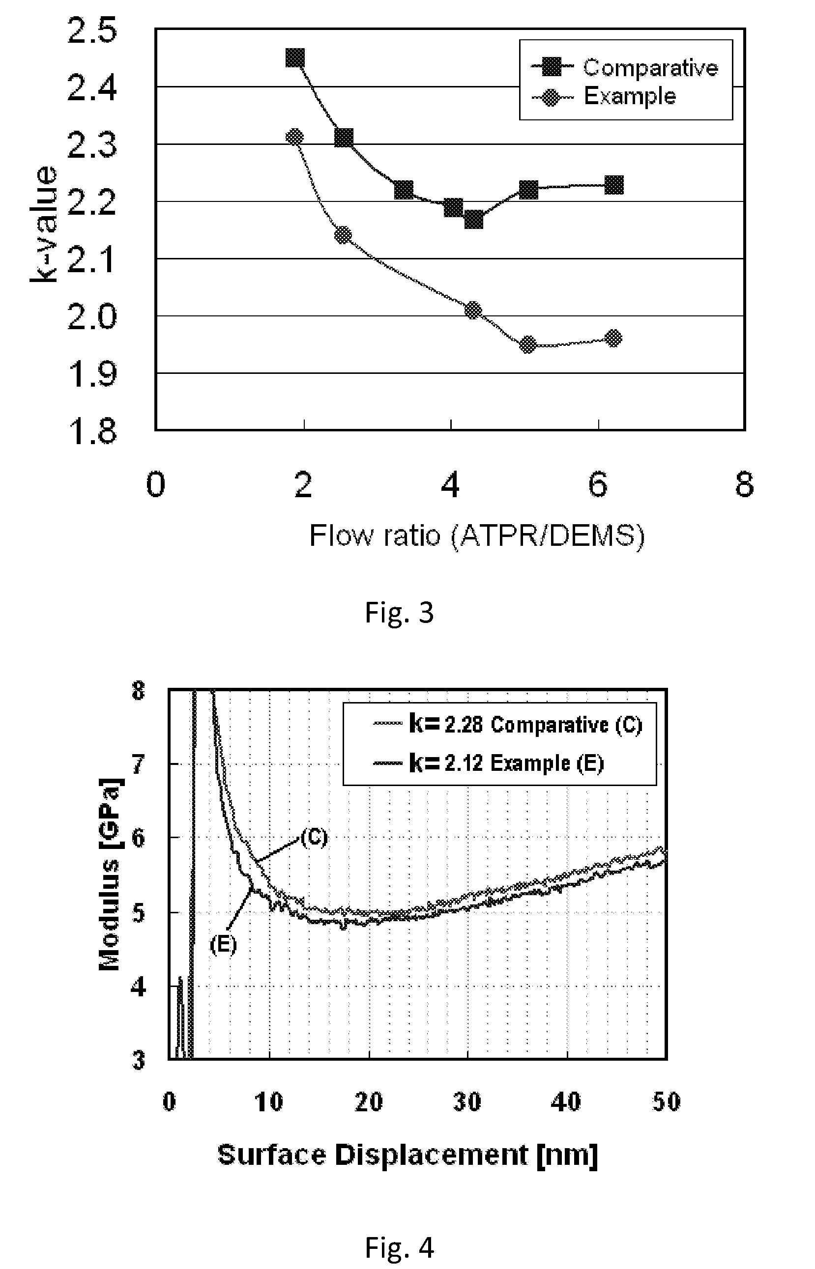
[0084]The dielectric constant of a film upon the UV-curing was 2.28, and it was reduce...

examples 3 and 4

[0085]The same processes were conducted as in Example 2 except the conditions shown in Table 1 below:

[0086]

TABLE 1H2RFTemperaturePressureFlowpowerGapIVH2 plasmaEx.[° C.][Pa][sccm][W][mm]k-value[A / cm2]treatment225030100100112.28→2.123.4E−8→2.2E−9Post-UV325030100100112.41→2.311.2E08→3.8E−9Post-UV42505020040082.17→1.961.3E−8→1E−9Pre-UV

[0087]As shown in Table 1, in Examples 2-4, the dielectric constant of the films were reduced by at least 0.1, and the leakage current was reduced nearly by one digit.


PUM

PropertyMeasurementUnit
pressureaaaaaaaaaa
temperatureaaaaaaaaaa
thicknessaaaaaaaaaa

Abstract

A method for reducing a dielectric constant of a film includes (i) forming a dielectric film on a substrate; (ii) treating a surface of the film without film formation, and (III) curing the film. Step (i) includes providing a dielectric film containing a porous matrix and a porogen on a substrate, step (ii) includes, prior to or subsequent to step (iii), treating the dielectric film with charged species of hydrogen generated by capacitively-coupled plasma without film deposition to reduce a dielectric constant of the dielectric film, and step (iii) includes UV-curing the dielectric film to remove at least partially the porogen from the film.

Description

BACKGROUND OF THE INVENTION[0001]1. Field of the Invention[0002]The present invention generally relates to a method for reducing a dielectric constant of a film, particularly to such a method for a film containing a pore generator (“porogen”) using direct plasma or capacitively-coupled plasma of hydrogen.[0003]2. Description of the Related Art[0004]These days, technology in the field of semiconductor manufacturing equipment shows remarkable improvement, achieving high integration, high speed, and high capacity, which makes wiring more fine. The more fine wiring becomes, the higher capacity the wiring requires, especially if the wiring is configured in multiple layers. As a result, such fine wiring causes signal delay, and increases electricity consumption. To solve these problems, and to reduce the amount of required capacity, insulating films having low dielectric constant have been used for multilayer wiring.[0005]Taking into consideration how future semiconductor manufacturing eq...

Claims


Application Information

Patent Timeline
Patent Type & Authority Patents(United States)
IPC IPC(8): H01L21/00H05C1/00H01L23/58H05H1/00
CPCH01L21/02126H01L21/02203H01L21/0234H01L21/02348C23C16/401C23C16/56
Inventor NAKANO, AKINORI
Owner ASM JAPAN
Why Eureka
Try Eureka