
Apparatus and method for the measurement of electrical conductivity and dielectric constant of high impedance fluids

a technology of electrical conductivity and dielectric constant, which is applied in the direction of fluid resistance measurement, resistance/reactance/impedence, instruments, etc., can solve the problems that the complexity of a multiple electrode system does not lend itself to low cost measurement of plural parameters of lubrication oil, and the operation characteristics such as capacitance off-setting capabilities are not suitable for use with this known hydrocarbon fuel sensor. , to achieve the effect of low component requirements and low cos

Active Publication Date: 2013-10-08
FALMOUTH SCI +1
View PDF8 Cites 3 Cited by
  • Summary
  • Abstract
  • Description
  • Claims
  • Application Information

AI Technical Summary

Benefits of technology

[0008]The present invention provides a sensor, system of measurement, and method of measurement of conductivity and dielectric constant of a fluid, particularly high impedance, hydrocarbon-based fluids, on a single pair of coaxial electrodes combined with unique sensor signal processors. This invention uses mutually compatible sensor geometry for the electrodes, i.e. a geometry that provides both the correct cell constant for conductivity of hydrocarbons fluids (typical range 0-100,000 pS / cm), and a sensor whose bulk capacitance (for use in dielectric constant measurement) in the range of measure of readily available low cost commercial IC's (having a typical capacitance measurement span of <10 pF, with a total bulk capacitance at the chip of <20 pF). A sensor with a geometry meeting these requirements is then used to form a very low cost system to accurately determine both conductivity and the dielectric constant of the fluid in question.
[0009]The ability to measure both parameters in the same volume of fluid has additional advantages as the measures can be correlated to better determine the “condition” of the hydrocarbon fluid and its ability to remain in service, e.g., lubricating large electrical power and marine diesel engines. The cell conductivity constant for use with hydrocarbon-based oils having a conductivity in the range of 1 to 500,000 pS / M is preferably less than or equal to about 0.1. The cell bulk capacitance of these sensors with hydrocarbon fluids inside results in a bulk capacitance of at least about 4 pF. Additionally, as they are measured on the same volume, they are made at the same temperature. This facilitates the application of thermal corrections to the physical values measured. The electrodes are preferably electrically insulated from a supporting frame by impedances exceeding that of the fluid being measured by several orders of magnitude.
[0010]In one embodiment, electronic circuitry is connected to this same geometry sensor with an electronic interface connected to a Microcontroller / Digital signal Processor (DSP). The Microcontroller / DSP both generates synchronous drive signals at various frequencies, while directly digitizing and numerically processing the sensor output. The digitized output is numerically processed in the Microcontroller / DSP into its in-phase and quadrature components from which conductivity and dielectric constant, respectively, are determined. This embodiment results in an even more simplified (lower component count) system. This reduces the required analog signal processing components, and, the complexity they require. The numerical processing of the signals also reduces processing errors typical of analog circuit processors. The Microcontroller DSP can vary 1) the frequency and amplitude of the sensor drive signals, and 2) the duration over which sample signals are processed (to extend the range or resolution of the sensor system). These changes can be then made in real time.
[0011]Stated on other words, the Microcontroller has complete control over the process, i.e. it can change the drive frequency to make higher resolution resistive or capacitive measures as needed. If the sensor signal is larger than expected, it can lower the amplitude, in essence thereby extending the range. On the measurement side the Microcontroller / DSP can use an in-phase and phase shifted reference (at the same time to make both measures). It can also choose to integrate the signal over more integer periods of the drive signal period. This reduces the bandwidth of the system, which in turn reduces noise and improves resolution, at the expense of overall sampling. With this much processing run by the Microcontroller / DSP, the sensor can “adapt” in real time to changing physical conditions in the fluid, or, to modify the data quality or quantity that the user may need.
[0012]Traditionally capacitance measures are made on dielectrically coated electrodes. This, of course, does not allow the measurement of electrical conductivity, as no current could flow. As the frequency of operation of the system is under Microcontroller / DSP program control, real time altering of the base frequency of operation eliminates the effects of the non coated electrodes, and or to extend the range resolution of the measures. As a result the present invention uses metal electrodes exposed (exposed meaning bare metal or equivalent electrically at least at their opposed, electrically-active surfaces) for both conductivity and dielectric constant measures.
[0014]The invention includes a system and method of operation using the single pair, preferably coaxial, electrode sensor. The system, or device, includes low cost integrated circuits for measuring the conductivity and dielectric constant of a high impedance fluid exposed to the sensor as well as a solid state interface between the sensor and these circuits. The interface bridges differences in the operating electrical parameters of these components, and either automatically switches between the operation of these circuits to produce measurements of conductivity and dielectric constant using only one sensor, or in the second method alters the drive signal and computation path to determine the components. The AC driving signals produced by these circuits are at low frequencies. The combination of a sensor according to the present invention (a single pair of coaxial, exposed metal electrodes defining a cell having the electrical characteristics noted above, and the aforementioned signal processor provides many of the advantages of the invention. In the form of the invention using a Microcontroller / DSP processor to control both drive signals to the sensor, and providing subsequent direct digital conversion with numerical processing of the received sensor signal, results in a sensor electronic system which is especially simple, has low component requirements, and nevertheless meets the resolution requirements for fluid conditioning monitoring.

Problems solved by technology

These developments were effective for the measurement of aviation turbine fuel, but the complexity of a multiple electrode system does not lend itself to a low cost measurement of plural parameters of lubrication oil and like hydrocarbon-based fluids.
Low cost IC's that can measure conductivity or capacitance are known, e.g. for use with touch panels, but their operating characteristics such as their input capacitance range and capacitance off-setting capabilities are not suitable for use with this known hydrocarbon fuel sensor.

Method used


Image

  • Apparatus and method for the measurement of electrical conductivity and dielectric constant of high impedance fluids
  • Apparatus and method for the measurement of electrical conductivity and dielectric constant of high impedance fluids
  • Apparatus and method for the measurement of electrical conductivity and dielectric constant of high impedance fluids

Examples


Embodiment Construction

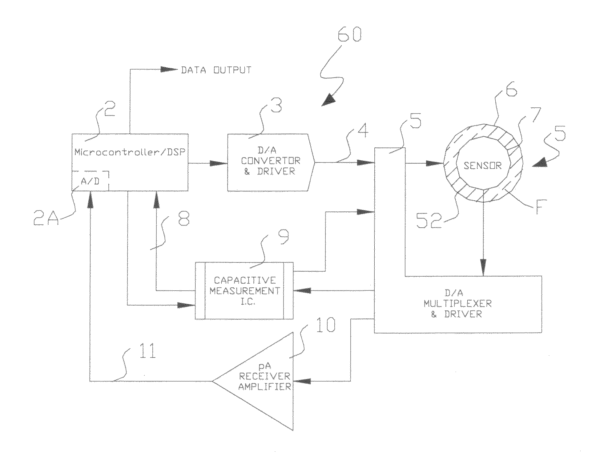
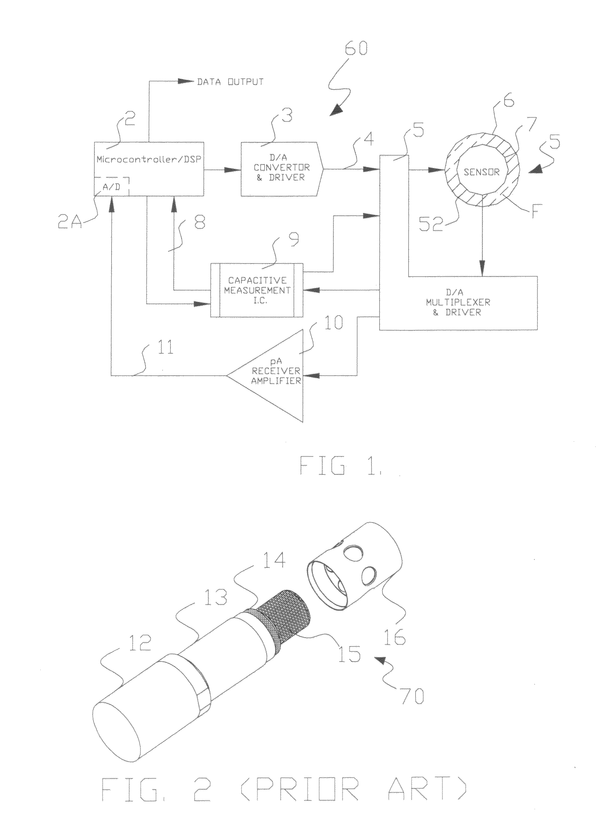
[0022]A sensor 50 according to this invention in the embodiment shown in FIG. 1 has a single pair of coaxial, bare metal electrodes 6, 7 that form a measurement cell 52 that holds a fluid F to be measured. In this exemplary embodiment, the sensor geometries and constants are adapted for a conductivity measurement system for jet fuel & lubricating oils with a range 0-2000 pS / cm (Pico-Siemens / centimeter) with a typical dielectric constant of 2 to 2.5. While the electrodes 6, 7 are preferably all bare metal, it will be understood that what is important is that the fluid F in the measurement cell 52 is in electrical connection with the surface of the electrodes forming that measurement cell 52.

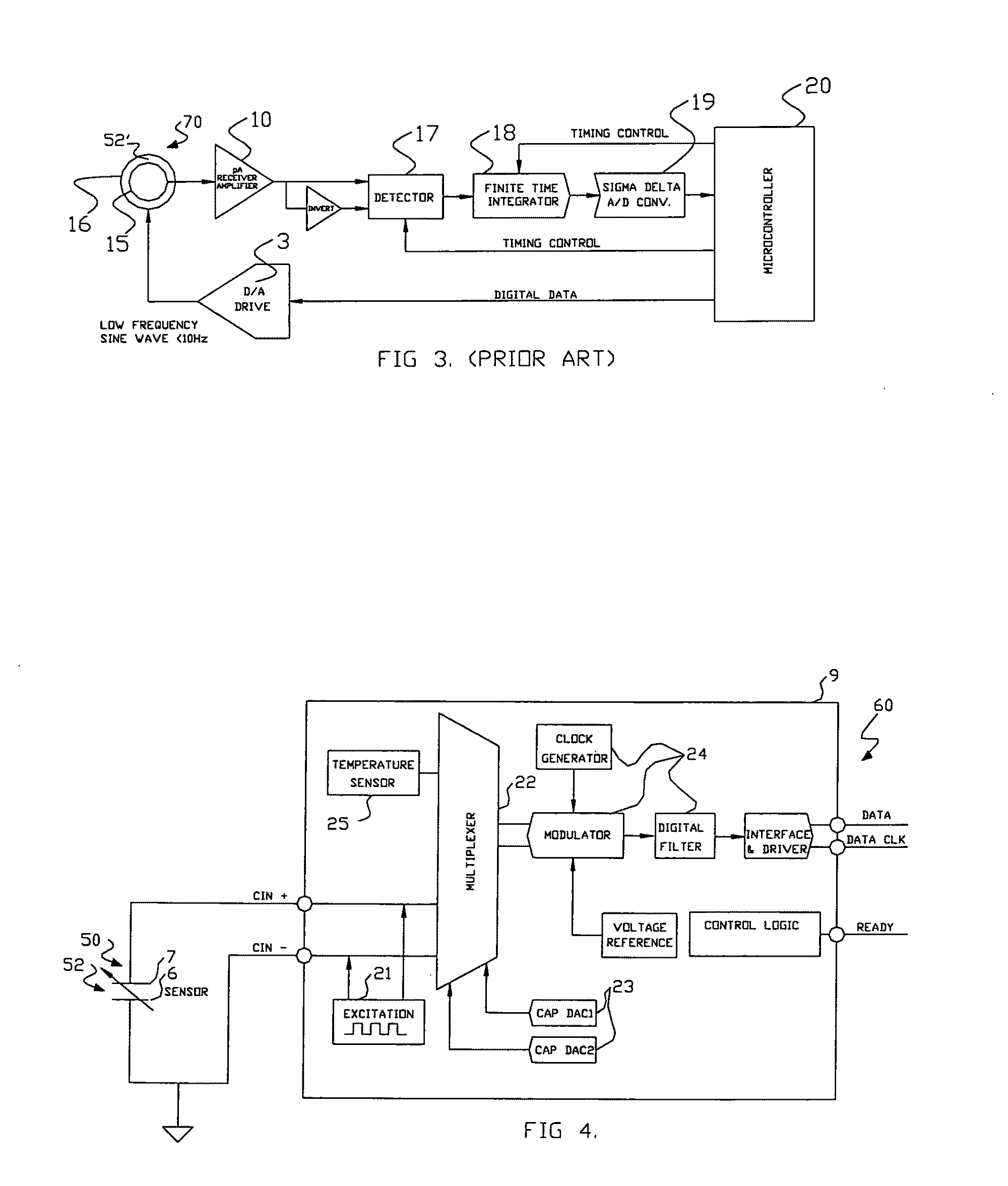
[0023]FIG. 1 also shows a multi-parameter measuring system 60 according to this invention having a novel electronic switching interface 5 that allows the combined parameter electrode sensor to interface with the two distinct measurement circuits 10 and 9 for conductivity and dielectric constant, r...


PUM


Abstract

A sensor, a system of direct measurement using that sensor, and a method of direct and simultaneous measurement of conductivity and dielectric constant of a fluid, particularly high impedance, hydrocarbon-based fluids. The sensor has a cell that holds the fluids to be measured between a single pair of coaxial, bare metal electrodes connected through interface circuitry to measurement circuitry preferably implemented in one or several IC's. The sensor has a mutually compatible electrode geometry that provides both the correct cell constant for measurement of conductivity of hydrocarbons fluids (typical range 0-100,000 pS / cm), and a bulk capacitance (for use in dielectric constant measurement) in the range of measure of readily available low cost commercial IC's (having a typical capacitance measurement span of <10 pF, with a total bulk capacitance at the chip of <20 pF). The cell conductivity constant for use with hydrocarbon-based oils having a conductivity in the range of 1 to 500,000 pS / M is preferably less than or equal to about 0.1. The cell bulk capacitance with hydrocarbon fluids inside the sensor results in a bulk capacitance of at least about 4 pF. In one embodiment, the electronic circuitry is a Microcontroller / DSP that both generates synchronous drive signals at various frequencies, for both conductivity and dielectric constant measurements while directly digitizing and numerically processing the sensor output.

Description

CROSS REFERENCE TO RELATED APPLICATIONS[0001]This application claims priority under 35 USC 119(e) of U.S. Provisional Application No. 61 / 206,289 filed Jan. 29, 2009, the disclosure of which is incorporated herein by reference.FIELD OF THE INVENTION[0002]The present invention relates generally to the electrical measurement of physical parameters of fluids, and more particularly to the direct measurement of both the conductivity and dielectric constant of high impedance, hydrocarbon-based fluids, such as lubrication oils, kerosene (jet fuel), hydraulic fluids, and, solvents (e.g. isoparg). However, this invention also has applicability across the range to hydrocarbon fluid electrical conductivity measures, from 0 pS / m to 0.1 μS / cm.BACKGROUND OF THE INVENTION[0003]There is a long-standing need to monitor or inspect the condition of various hydrocarbon-based fluids such as aviation kerosene, lubricants and inks that are stored or flowing. Devices and techniques for the electrical measur...

Claims


Application Information

Patent Timeline
Patent Type & Authority Patents(United States)
IPC IPC(8): G01R27/08
CPCG01N27/02G01R27/22G01R27/2647G01N33/2823
Inventor FOUGERE, ALAN J.
Owner FALMOUTH SCI
Learn More