
Heated fluid conduit end covers, systems and methods

a fluid conduit and end cover technology, applied in the field of fluid conduits, can solve the problems of difficult fluid passing through the coupling, inefficient and inflexible solution, adverse effect on equipment and hydraulic components of drill rigs, etc., to prevent moisture from interrupting the heating of the hose, and eliminate moisture from migrating

Active Publication Date: 2013-10-15
THE GATES CORP
View PDF32 Cites 19 Cited by
  • Summary
  • Abstract
  • Description
  • Claims
  • Application Information

AI Technical Summary

Benefits of technology

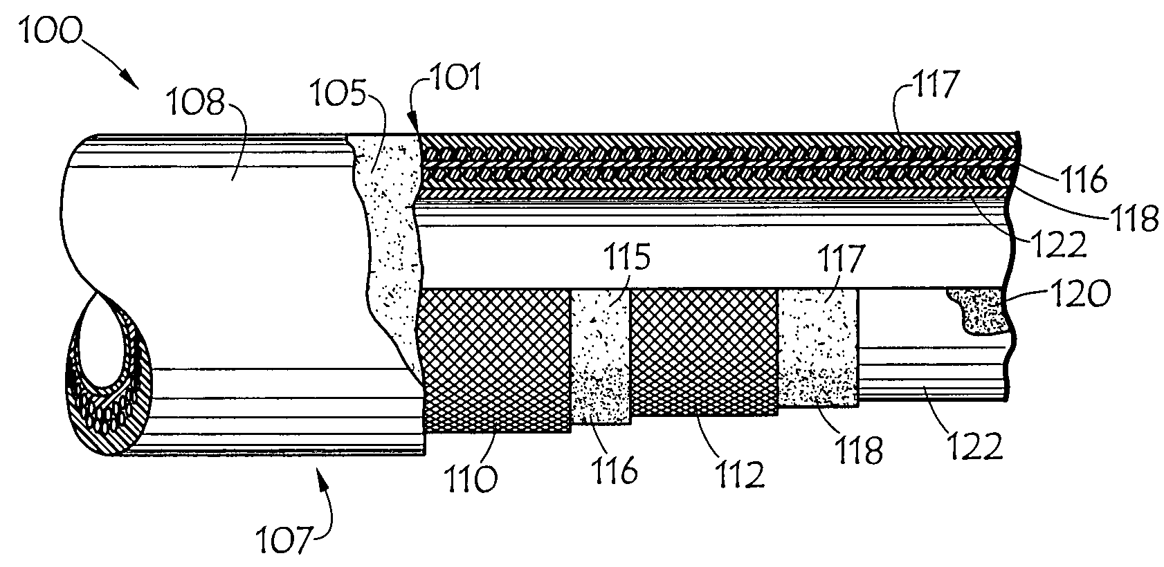
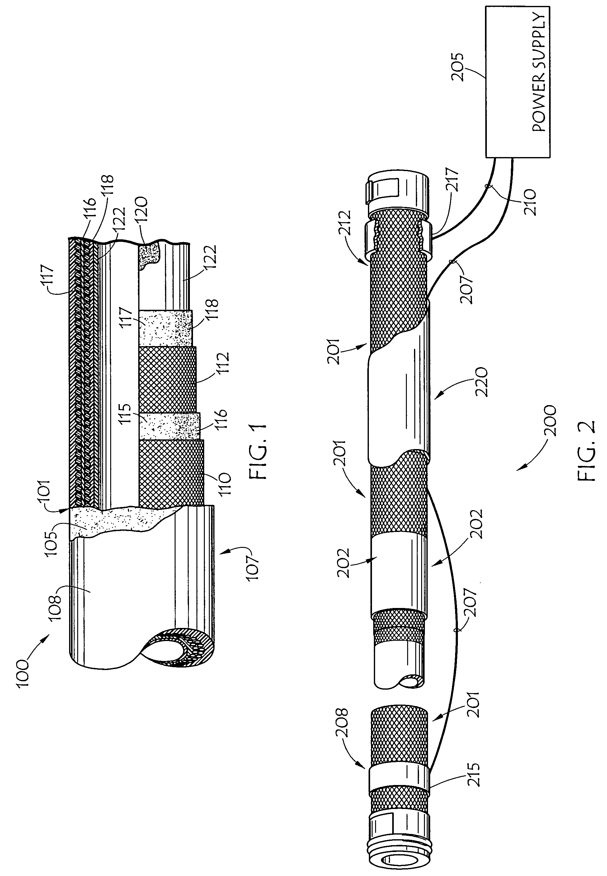
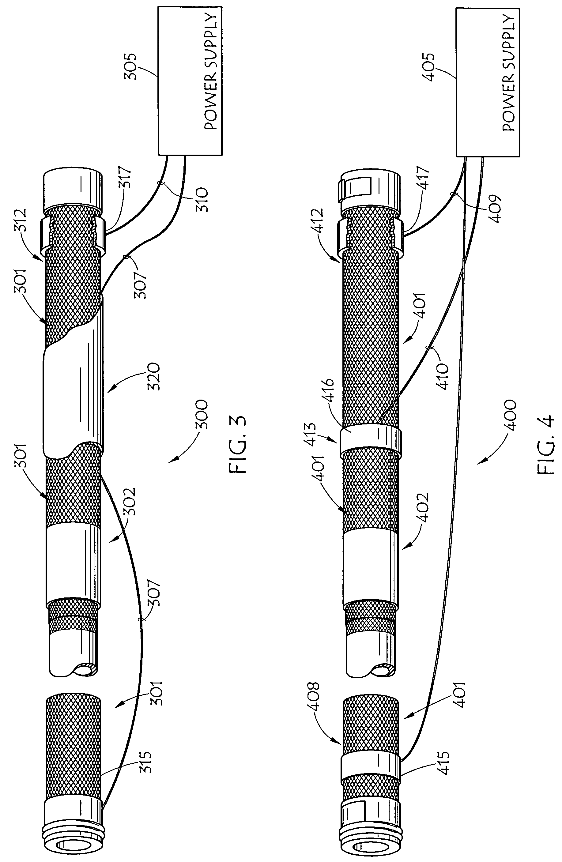
The present invention relates to a heated fluid conduit that includes a semi-conductive material, such as a resistance heating tube or a carbon fiber tensile member, along with an electrical power supply and a sealing end cover to prevent moisture from interrupting heating. The heating system can be tailored to individual conduit lengths, and the hose can be covered from moisture to allow for a water submersible heated hose assembly. The technical effects include improved heating efficiency, protection against damage from fluid, and improved fluid flow without damage to components.

Problems solved by technology

This is a rather inefficient and inflexible solution that requires a complete redesign of the fluid line to change its heating properties.
This cold weather has an adverse effect on equipment and hydraulic components on a drill rig.
If the couplings are not warmed with the hose, it may be difficult for fluid may to pass through the couplings.
Since heated SCR or hydraulic hoses may often be exposed to the elements (i.e. rain and snow), directly or indirectly, during use, the potential exists for moisture to penetrate the hose end and interrupt the electrical connection.
Most manufacturers of SCR hose use a snap over cover that does not eliminate the entrance of moisture to the end fittings, leading to interruption of the electrical connection.
This in turn will interrupt the heating of the hose until it dries out.
The interruption of the heating of the hose and fluid within the hose is not desirable.

Method used


Image

  • Heated fluid conduit end covers, systems and methods
  • Heated fluid conduit end covers, systems and methods
  • Heated fluid conduit end covers, systems and methods

Examples


embodiment 800

[0045]FIGS. 5, 6 and 7 are perspective illustrations of embodiments of covers 500, 600 and 700 for use with various embodiments of the present heated fluid conduits and / or fluid conduit heating systems. FIG. 8 is a partially fragmented illustration of embodiment 800 of a fluid conduit heating system in accordance with the present invention employing coupling covers similar to cover 500 and 600 illustrated in FIGS. 5 and 6.

[0046]Covers 500, 600 and 700 provide protection and insulation for quick-connect couplings and wiring, such as conductors 807 and 810, associated with a heated fluid conduit in accordance with various embodiments of the present invention. The embodiments of covers 500, 600 and 700 shown are comprised of paired molded plastic parts, placed together to form a hard protective coverings for the couplings and the wiring. The illustrated covering embodiments each comprise two pieces, which are generally mirror images of each other, 501 and 502, 601 and 602, and 701 and ...

embodiment 900

[0051]FIG. 9 is a partially fragmented illustration of embodiment 900 of a heated fluid conduit of the present invention employing molded end covers 901 and 902. In accordance with the present invention, heated fluid conduit 900 might, similar to conduit 100, have a body with a semi-conductive material disposed therein and one or more wires 905 and 906 coupling electrical power supply 908 to the conduit to provide a voltage across the conduit and an electrical current therethrough to heat the fluid conduit. However, conduit 900 also employs end covers 901 and 902, molded over a fitting or the like fitted to an end of the conduit. Overmolded end covers 901 and / or 902 may also be molded over an end of wire 905, facilitating coupling of power supply 908 to an end of the conduit. Similar to as discussed above, electrical power supply 908 may be coupled to each end of the conduit, and also possibly another terminal of the electrical power supply may be couple to the conduit at one or mor...

embodiment 1000

[0053]FIG. 10 is a perspective illustration of embodiment 1000 of a fluid conduit heating system in accordance with the present invention employing molded fitting covers 1001 and 1002. fluid conduit heating system 1000, may employ semi-conductive sleeve 1005 disposed over fluid conduit 1010 with sleeve 1005 extending at least partially over a fitting fitted to an end of conduit 1010. Electrical power supply 1008 may be coupled to each end of sleeve 1005 to provide a voltage across sleeve 1005 and a resulting electrical current through semi-conductive sleeve 1005 to heat sleeve 1005 and fluid conduit 1010, within. End covers 1001 and 1002 are preferably molded over at least a portion of the fitting and the sleeve extending thereover. At least one of the terminals of electrical power supply 1008 is preferably coupled to ends of sleeve 1005, such as by wires 1006 and 1007, and one terminal of the electrical power supply may be coupled to sleeve 1005 at one or more points therebetween, ...


PUM


Abstract

A fluid conduit body having a semi-conductive material disposed therein and at least one wire coupling an electrical power supply to the conduit to provide an electrical current therethrough to heat the fluid conduit also has an end cover molded over a fitting fitted to an end of the conduit and over an end of the wire coupling the power supply to an end of the conduit. Alternatively, a fluid conduit heating system employs a semi-conductive sleeve disposed over a fluid conduit with the sleeve extending at least partially over a fitting fitted to an end of the conduit. An electrical power supply is coupled to each end of the sleeve to provide an electrical current through the semi-conductive sleeve to heat the sleeve and the fluid conduit. An end cover is molded over at least a portion of the fitting and the sleeve extending thereover.

Description

CROSS-REFERENCE TO RELATED APPLICATION[0001]This is a continuation in part of U.S. patent application Ser. No. 12 / 378,435, entitled Heated Fluid Conduits, Systems and Methods, Filed Feb. 13, 2009, which is incorporated herein by reference.BACKGROUND OF THE INVENTION[0002]1. Field of the Invention[0003]This invention relates generally to fluid conduits such as hoses and tubes, more particularly to heated fluid conduits such as fluid conduits heated using semiconductive resistance heating, and specifically to molded, preferably waterproof connector ends for such hoses.[0004]2. Description of the Prior Art[0005]Selective Catalytic Reduction (SCR) vehicles, referred to in Europe as Euro V vehicles, are diesel powered motor vehicles which are compatible with the use of an operating fluid to reduce emissions. Typically, the SCR vehicle has a urea tank, separate from the fuel tank, which is used to carry an operating fluid such as an automotive urea solution, or the like. Automotive Urea S...

Claims


Application Information

Patent Timeline
Patent Type & Authority Patents(United States)
IPC IPC(8): E03B7/10F16L53/37
CPCF16L53/007F16L53/37Y02A50/20Y02T10/12H05B1/0291
Inventor ELLIS, MICHAEL H.DEANS, TIMOTHYTWAROG, EVANGILBREATH, DONALD R.BOLGER, WALKERSAUPE, TIM
Owner THE GATES CORP
Learn More