Electron transfer dissociation device

a technology of electron transfer and dissociation device, which is applied in the direction of mass spectrometer, dispersed particle separation, separation process, etc., can solve the problems of large mass to charge ratio range of analyte and reagent ions which can be confined simultaneously within the ion trap in order to promote ion-ion reaction, and achieve the effect of maximising the efficiency of fragment ion

Active Publication Date: 2013-10-22
MICROMASS UK LTD
View PDF19 Cites 4 Cited by
  • Summary
  • Abstract
  • Description
  • Claims
  • Application Information

AI Technical Summary

Benefits of technology

[0021]In another mode of operation the control system may be arranged and adapted to vary, alter, increase or decrease the one or more parameters in order to minimise and / or reduce the fragmentation and / or charge reduction of the first ions so that the ion guide is operated in an ion guiding mode wherein ions received at the input to the ion guide are substantially onwardly transmitted to the output of the ion guide without substantially being subjected to fragmentation and / or charge reduction,
[0150]According to an embodiment of the present invention a new method of Data Directed Analysis (“DDA”) is provided that incorporates real time monitoring of the ratio of the intensities of the charge reduced cations or charge reduced analyte ions to the intensity of non-charged reduced the parent cations within a product ion spectrum. The ratio is preferably used to control instrumental parameters that regulate the degree of Electron Transfer Dissociation and / or Proton Transfer Reaction. As a result the fragment ion efficiency may be maximised in real time and on timescales which are comparable with chromatography (LC) peak elution time scales.

Problems solved by technology

However, the technique of Electron Capture Dissociation suffers from the significant problem that it is necessary simultaneously to confine both positive ions and electrons at near thermal kinetic energies.
However, such mass spectrometers are very large and are prohibitively expensive for the majority of mass spectrometry users.
However, this approach is problematic since the effective RE pseudo-potential barrier height observed by an ion within the ion trap will be a function of the mass to charge ratio of the ion.
As a result, the mass to charge ratio range of analyte and reagent ions which can be confined simultaneously within the ion trap in order to promote ion-ion reactions is somewhat limited.
It can be difficult to know a priori the optimal parameters for every anion-cation combination from an LC run.

Method used


Image

  • Electron transfer dissociation device
  • Electron transfer dissociation device
  • Electron transfer dissociation device

Examples


Embodiment Construction

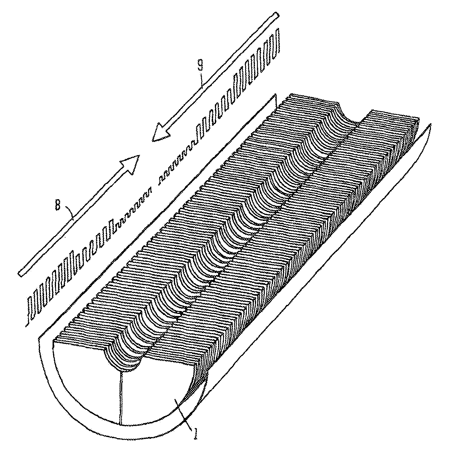
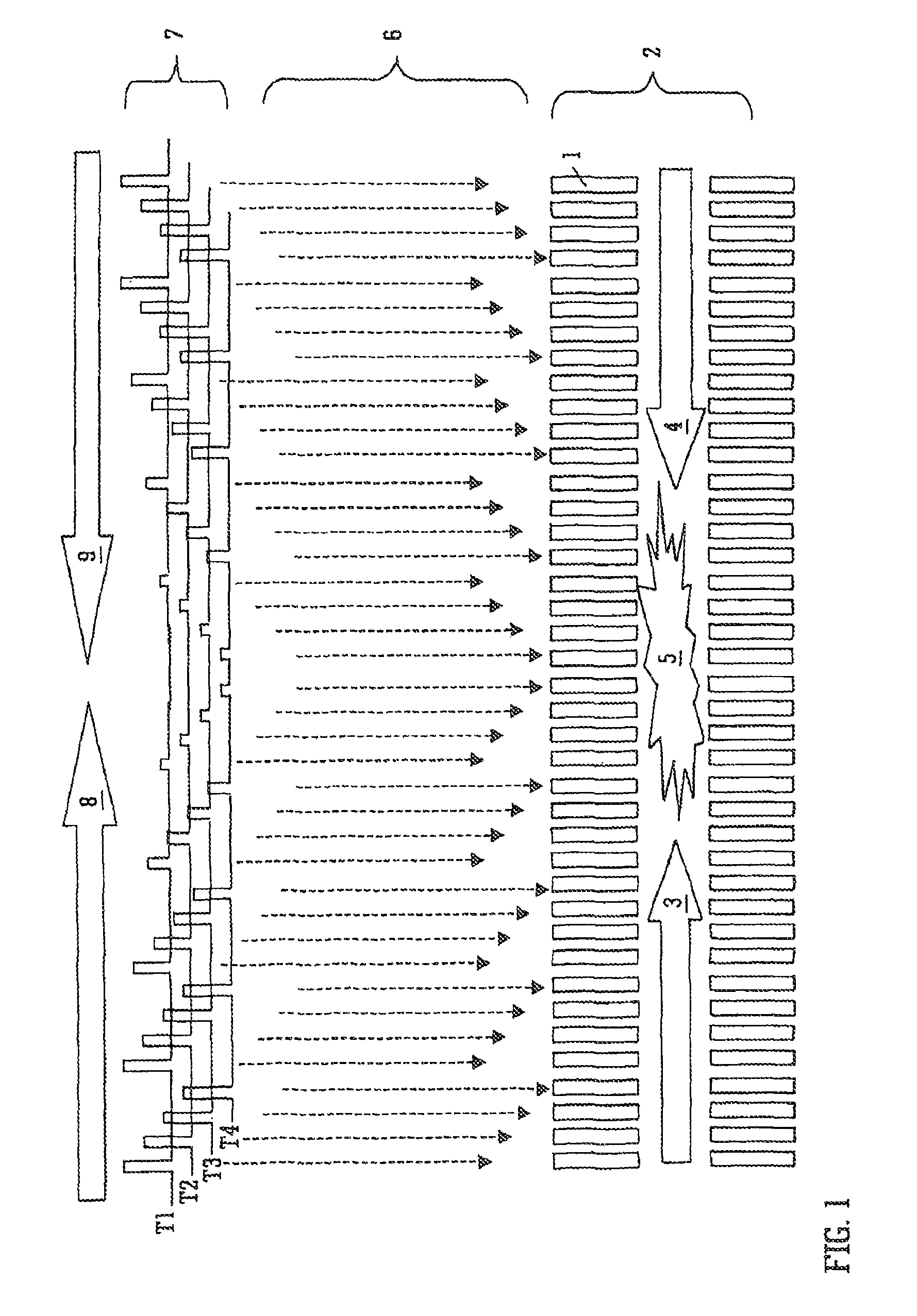
[0166]Various embodiments of the present invention will now be described. FIG. 1 shows a cross sectional view of the lens elements or ring electrodes 1 which together form a stacked ring ion guide, ion-ion reaction device or ion-neutral gas reaction device 2 according to a preferred embodiment of the present invention.

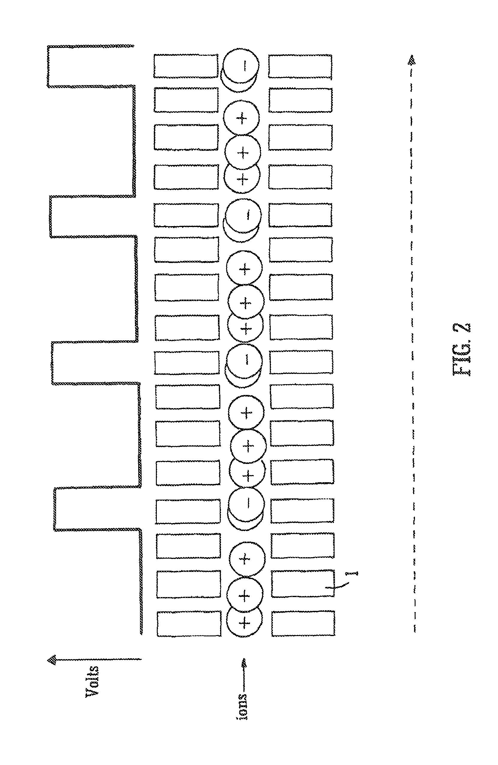
[0167]The ion guide, ion-ion reaction device or ion-neutral gas reaction device 2 preferably comprises a plurality of electrodes 1 having one or more apertures through which ions are transmitted in use. A pattern or series of digital voltage pulses 7 is preferably applied to the electrodes 1 in use. The digital voltage pulses 7 are preferably applied in a stepped sequential manner and are preferably sequentially applied to the electrodes 1 as indicated by arrows 6. According to an embodiment as illustrated in FIG. 1, a first DC travelling wave 8 or series of transient DC voltages or potentials is preferably arranged to move in time from a first (upstream) end of the io...


PUM


Abstract

A mass spectrometer is disclosed comprising an Electron Transfer Dissociation device comprising an ion guide. A control system determines the degree of fragmentation and charge reduction of precursor ions within the ion guide and varies the speed at which ions are transmitted through the ion guide in order to optimise the fragmentation and charge reduction process.

Description

CROSS REFERENCE TO RELATED APPLICATIONS[0001]This application is a continuation of U.S. patent application Ser. No. 13 / 937,806 filed Nov. 18, 2010, which is the National Stage of International Application No. PCT / GB2009 / 000902, filed Apr. 3, 2009, which claims priority to and benefit of United Kingdom Patent Application No. 0806725.8, filed Apr. 14, 2008 and U.S. Provisional Patent Application Ser. No. 61 / 049,495, filed May 1, 2008. The entire contents of these applications are incorporated herein by reference.BACKGROUND OF THE INVENTION[0002]The present invention relates to a method of mass spectrometry and a mass spectrometer for the acquisition of optimized Electron Transfer Dissociation (“ETD”) data.[0003]The present invention relates to an ion-ion reaction or fragmentation device and a method of performing ion-ion reactions or fragmentation. The present invention also relates to an Electron Transfer Dissociation and / or Proton Transfer Reaction device. Analyte ions may be fragme...

Claims


Application Information

Patent Timeline
Patent Type & Authority Patents(United States)
IPC IPC(8): H01J49/28
CPCH01J49/0072H01J49/28H01J49/065H01J49/0045
Inventor BROWN, JEFFERY MARKGREEN, MARTIN RAYMOND
Owner MICROMASS UK LTD
Why Eureka
Try Eureka