
System and method for parametric intercoupling of static and dynamic analyses for synergistic integration in electronic design automation

a technology of parametric intercoupling and electronic design, applied in the field of system and method for parametric intercoupling of static and dynamic analyses for synergistic integration of electronic design automation, can solve the problems of inefficiency of design flow, no provision for optimizing the electronic design at hand, and no automatic coordination of respective analysis tools. , to achieve the effect of promoting design flexibility and saving tim

Inactive Publication Date: 2013-10-22
CADENCE DESIGN SYST INC
View PDF10 Cites 22 Cited by
  • Summary
  • Abstract
  • Description
  • Claims
  • Application Information

AI Technical Summary

Benefits of technology

The patent is for a system and method that aims to save time and promote design flexibility in optimizing and verifying electronic system designs. The technical effect of this invention is more efficient and flexible designing of electronic systems.

Problems solved by technology

There is no automated coordination of the respective analysis tools to assist and enhance the operation of one in light of the other.
Consequently, there is no provision for optimizing the electronic design at hand, though the use of the analysis tools may preserve compliance with the applicable constraints at different stages of design.
This has lead to design flow inefficiencies yielding less than optimal designs.
Unfortunately, the goal in such exercises is to just ensure satisfaction of the many applicable constraints, rather than ensuring optimal design by providing sufficient margins on all constraints.
Moreover, the manual calculations of timing-budget are not only time-consuming and prone to error, they fail to adequately reflect dynamic SI effects that would arise during actual operation of the electronic system under design.
Rigid adherence to universal specifications and recommendations such as these, however, tends to inhibit flexibility in design.
The broad applicability inherent to manufacturers' specifications and recommendations is also likely to reflect aspects of conservative over-design, which may be good for sustained operability under wide ranges of conditions but bad for optimization of the design at hand.
While such design-in-kits heretofore known in the art provide a set of models, methods, automation and reference designs (of certain IP cores) which help to make for faster design cycle, they facilitate but a piece-meal approach to the use of their resources, offering no systematic methodology by which a designer is guided to make synergistic inter-coupled use of the same.
The kits' capabilities are made available for use in isolation to verify compliance with constraints at different stages of design, but not in any parametrically integrated manner sufficient to guide a methodical approach also towards optimal design.
While various analysis tools—such as for static timing analysis (based on transaction-based timing models) and dynamic SI analysis (based on real-time circuit simulations)—may be at their disposal, designers are not guided with any coordinated data exchange between the static and dynamic analysis tools.
Hence, practicable measures for timing-closure with pre-route and post-route SI simulations are not readily available.
While real-time simulation resources may be available on comprehensive design and analysis platforms for use in more exhaustive timing-verification, conducting such exhaustive timing verification at an SI or other electrical integrity analysis stage is much too time-consuming and difficult to be practicable in most applications.

Method used


Image

  • System and method for parametric intercoupling of static and dynamic analyses for synergistic integration in electronic design automation
  • System and method for parametric intercoupling of static and dynamic analyses for synergistic integration in electronic design automation
  • System and method for parametric intercoupling of static and dynamic analyses for synergistic integration in electronic design automation

Examples


Embodiment Construction

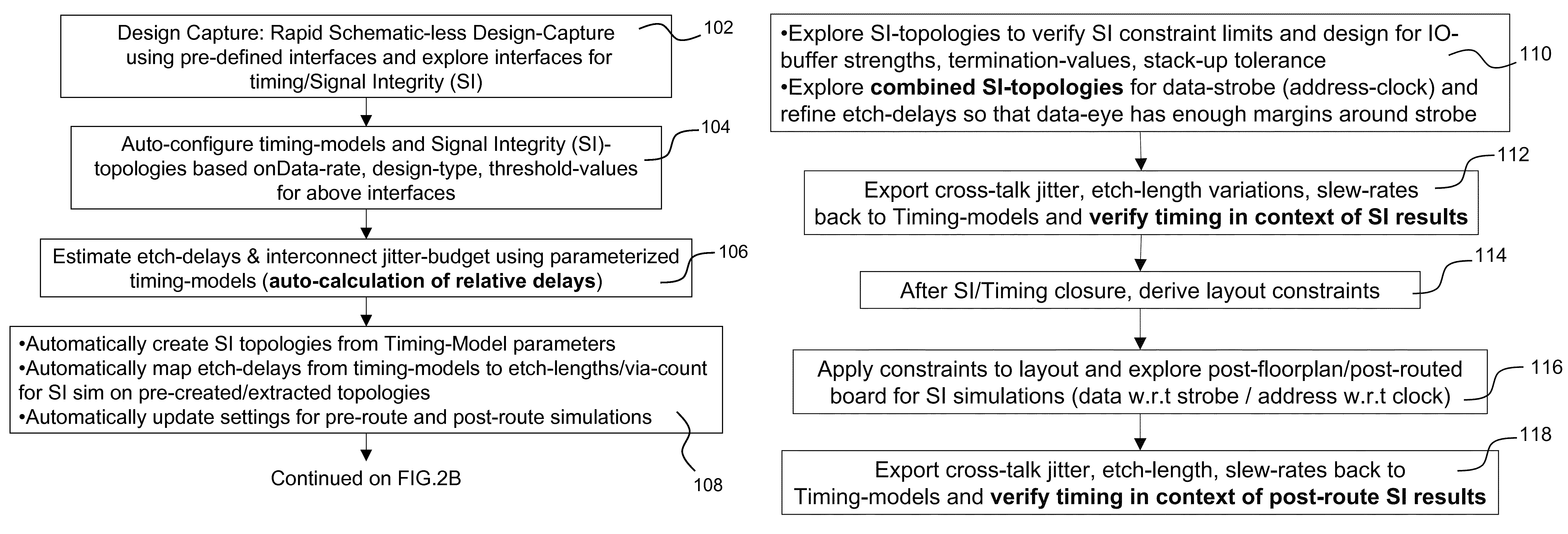
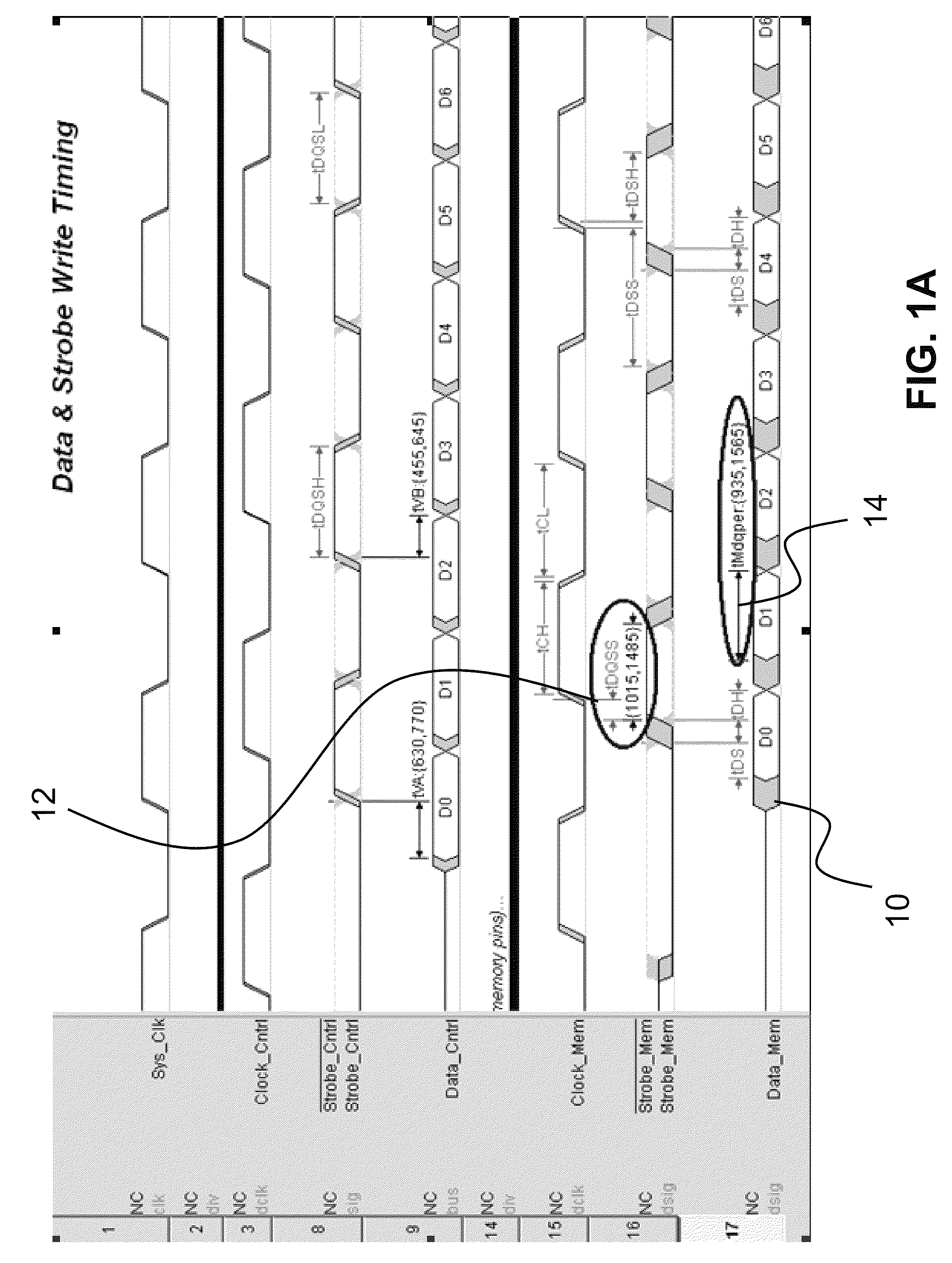
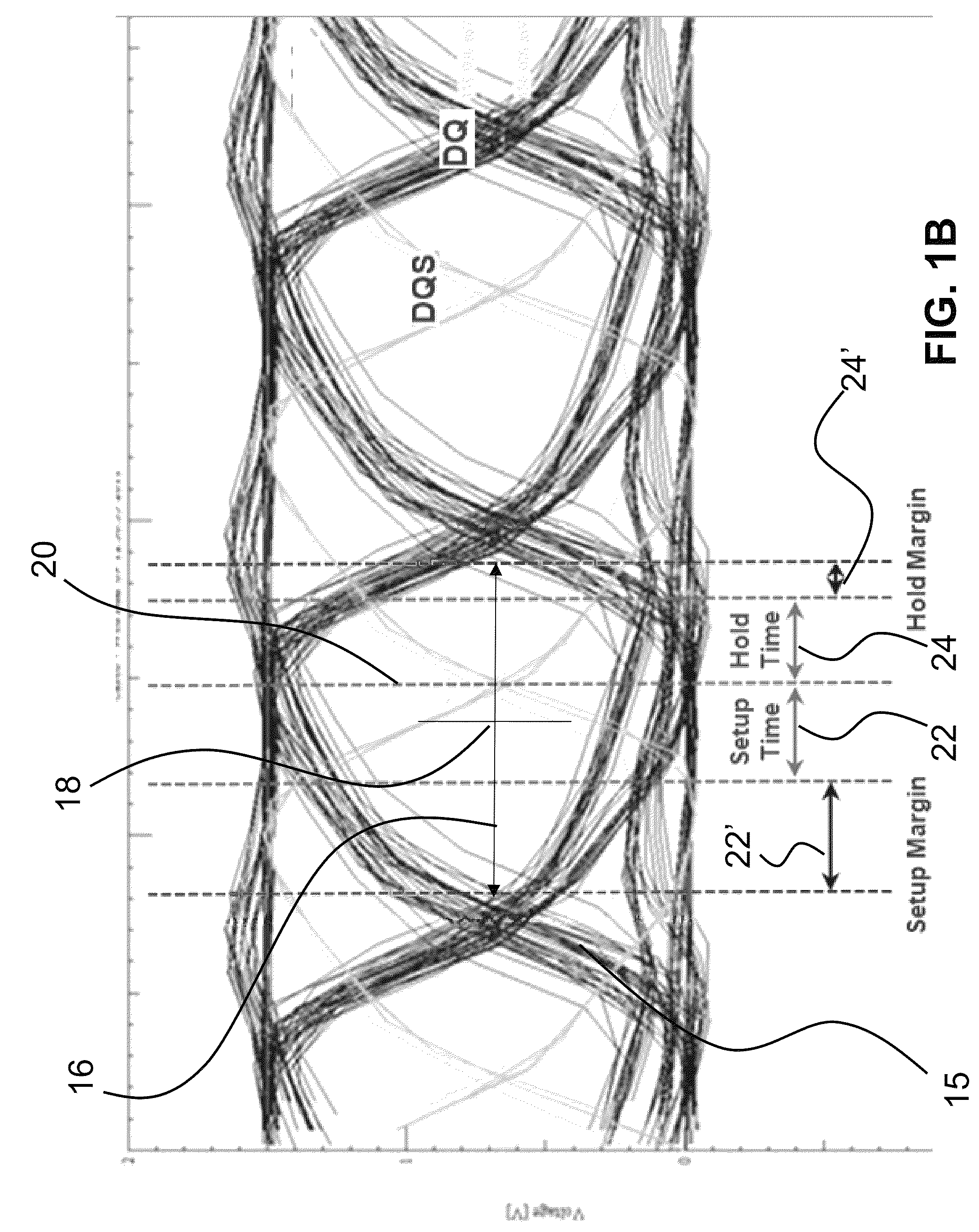
[0041]Signals within a system may generally be modeled as a voltage waveform transmitted from some driver portion of an electronic system to some receiver portion. In a digital application, the signal is normally defined by a stream of binary voltage values passed between the driver and receiver portions, which may be represented in simulated environments by corresponding behavioral models (such as IO buffer models). Signal integrity (SI) analysis is conducted using transient simulation on a corresponding SI topology (an effective circuit based on such behavioral models) between the driver and receiver portions, with suitable stimulus signals.

[0042]Simulation-based analyses, such as Signal Integrity (SI) analyses, are ways to establish the baseline performance of electronic system designs before expending valuable resources in prototyping the same. These analyses are carried out using suitable simulation and analysis tools. In the case of SI analysis, the analysis is carried out usi...


PUM


Abstract

A system and method are provided for actuating static and dynamic analysis tools in parametrically intercoupled manner for synergistic optimization of an electronic system design. The system and method execute a timing designer process for selectively actuating the static analysis tool to conduct timing analysis based on at least one predetermined timing model and generate a plurality of estimated values for certain signal parameters to be in compliance with predetermined timing constraints. A signal exploration process is executed to receive the estimated values from the timing designer process and configure the resources of the dynamic analysis tool responsive thereto. The signal exploration process actuates the dynamic analysis tool to conduct electrical integrity analysis based on transient simulation and generate a plurality of simulated values for signal parameters. The simulated values are back annotated to the timing designer process for timing closure.

Description

BACKGROUND OF THE INVENTION[0001]The subject system and method are generally directed to parametrically integrating static and dynamic analyses conducted in connection with an electronic design cycle. The system and method provide automated measures for the intercoupling of static and dynamic analyses by the synergistic exchange of parametric data therebetween, whereby such static analyses as for electronic circuit timing and such dynamic analyses as for simulation-based electrical integrity are enhanced in concert. The system and method thereby enable systematic verification and optimization of an electronic system design.[0002]With the ongoing trend of electronic system implementations growing in sophistication and complexity, it is increasingly important to quickly and accurately analyze different aspects of an electronic system's operation at various stages of its electronic design cycle. For example, a static timing analysis (STA) is normally conducted during an early stage of ...

Claims


Application Information

Patent Timeline
Patent Type & Authority Patents(United States)
IPC IPC(8): G06F17/50G06G7/62G06F11/22G06F9/455
CPCG06F17/5031G06F17/504G06F2217/84G06F30/3312G06F30/3323G06F2119/12
Inventor KUKAL, TARANJITDUDEK, HEIKOLONG, JERRY ALANBANTON, CHRIS
Owner CADENCE DESIGN SYST INC
Learn More