
Regenerative ion exchange fuel cell

Inactive Publication Date: 2013-10-29
EXCELLATRON SOLID STATE
View PDF59 Cites 13 Cited by
  • Summary
  • Abstract
  • Description
  • Claims
  • Application Information

AI Technical Summary

Benefits of technology

This patent describes a type of fuel cell that uses an ion conductor to transfer electricity. The fuel cell has a cathode and an anode, with a layer of electrolyte solution in between. The feature that makes this fuel cell special is that it also has a proton conductor which helps to move protons from the anode to the cathode. This design allows for more efficient fuel cell operation.

Problems solved by technology

The performance of conventional lithium battery systems is limited because they must include cathode materials that constrain the energy storage capacity of these cells on a per unit volume and mass basis.

Method used


Image

  • Regenerative ion exchange fuel cell
  • Regenerative ion exchange fuel cell
  • Regenerative ion exchange fuel cell

Examples


Embodiment Construction

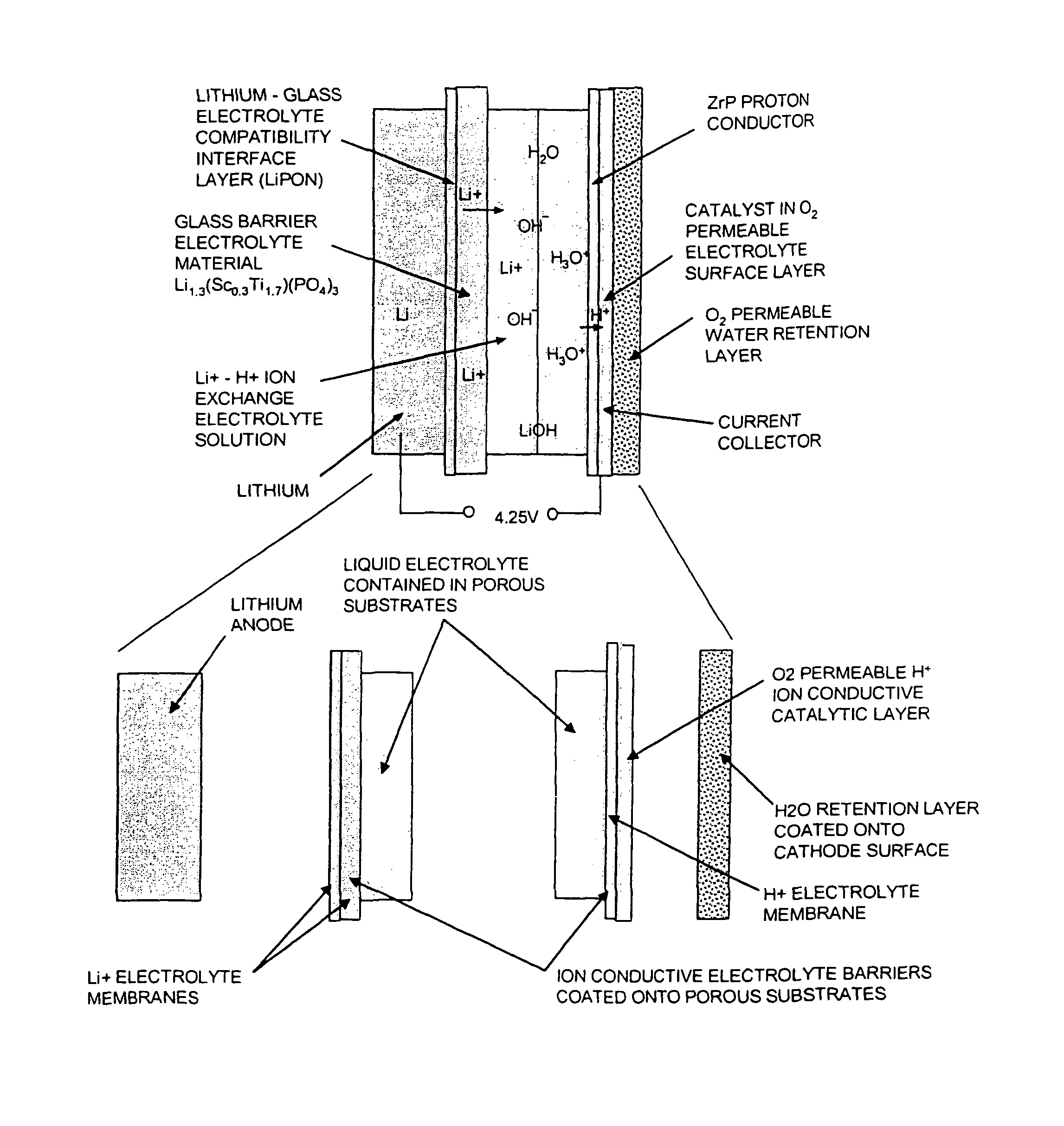
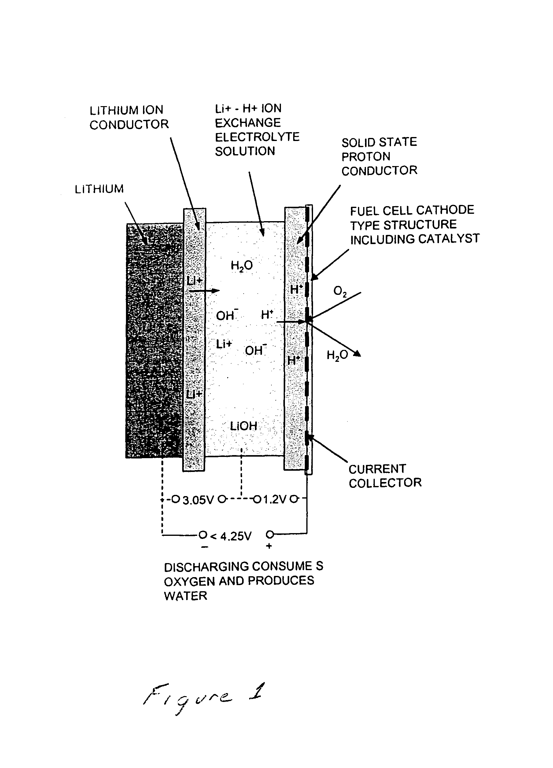
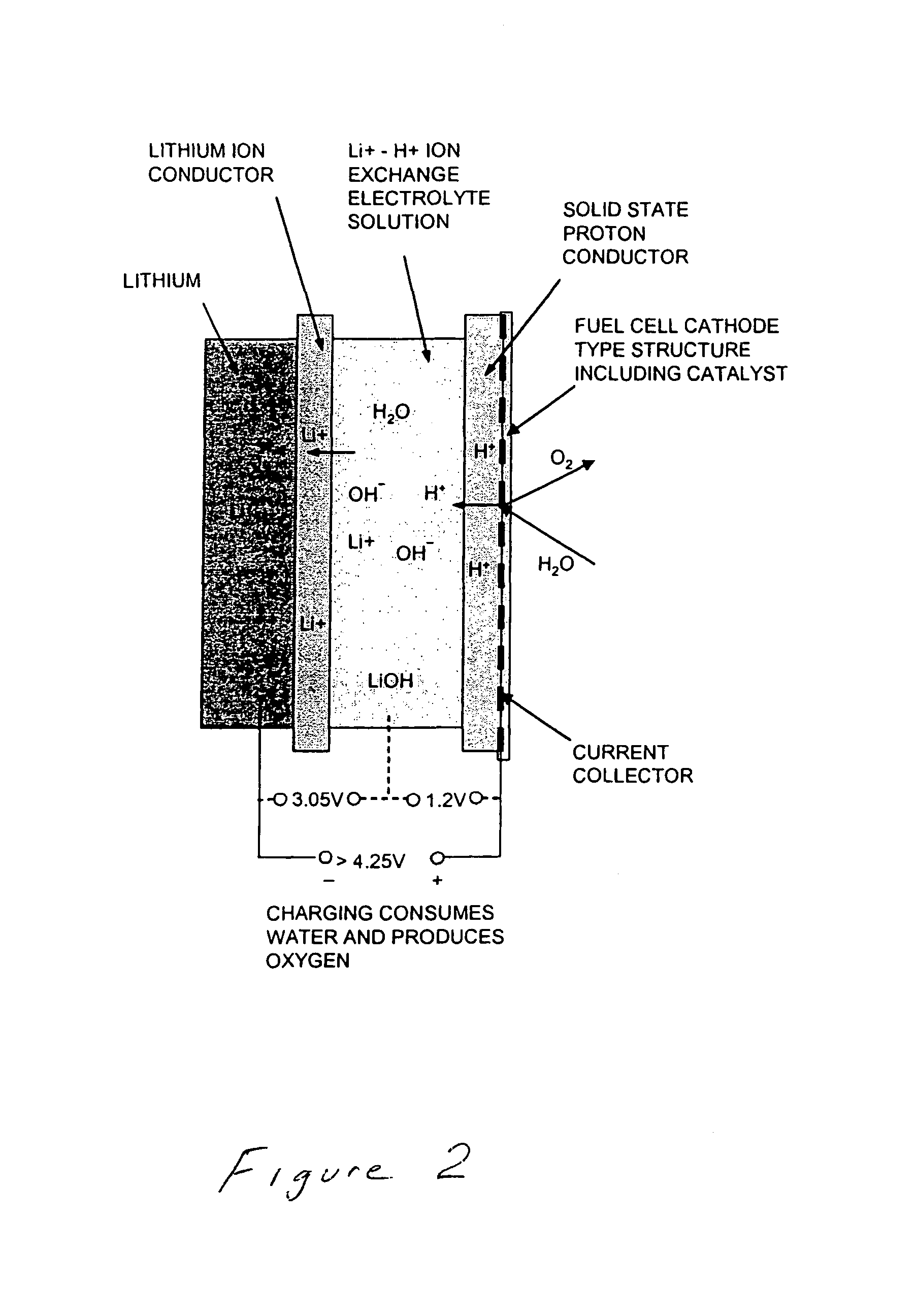
[0013]The explosive energy potential produced by this cell in the form of accumulated hydrogen and oxygen suggests that a more optimal cell design may be possible that could have even higher energy storage potential. One could use a fuel cell to generate electrical energy using the hydrogen and oxygen; however, the associated tanks and gas transport requirements would have an overall degrading impact on energy density. However, if this energy can be harvested efficiently, it represents a further energy gain in the basic battery system. FIGS. 1 and 2 suggest the general structure of such a combined cell, indicating the required layers and transport processes for a functional cell. The proposed system shown in FIGS. 1 and 2 indicate how the energy of the hydrogen can be simultaneously harvested resulting in a safe reversible lithium battery with high energy density. The actual cell may require additional layers for material compatibility or structural reasons.

[0014]The key to this new...


PUM


Abstract

A regenerative ion exchange fuel cell having an anode, a metal ion conductor coupled to the anode, an aqueous electrolyte solution positioned adjacent the metal ion conductor, a proton conductor mounted adjacent the aqueous electrolyte solution opposite the metal ion conductor, a cathode positioned adjacent the proton conductor opposite the aqueous electrolyte solution, and a cathode current collector associated with the cathode.

Description

REFERENCE TO RELATED APPLICATIONS[0001]This is a continuation-in-part of U.S. Patent Application Ser. No. 60 / 602,579 filed Aug. 18, 2004.TECHNICAL FIELD[0002]This invention relates to ion exchange fuel cells.BACKGROUND OF THE INVENTION[0003]The performance of conventional lithium battery systems is limited because they must include cathode materials that constrain the energy storage capacity of these cells on a per unit volume and mass basis. Typically, cathode materials include inorganic or organic compounds such as manganese oxide, vanadium oxide, lithium cobalt oxide and (CF)n. Although lithium has the highest columbic capacity, most available cathode materials have specific capacities that are less than 200 mAh / g. Metal / oxygen batteries offer high performance because cathode active materials are not stored in the battery. Oxygen from the environment is reduce at a catalytic air electrode surface forming either an oxide or peroxide ion that then reacts with cationic species in th...

Claims


Application Information

Patent Timeline
IPC IPC(8): H01M4/02
CPCH01M8/186H01M10/052H01M12/08Y02E60/122Y02E60/528H01M10/0562Y02E60/10Y02E60/50
Inventor JOHNSON, LONNIE G.
Owner EXCELLATRON SOLID STATE
Learn More