Method and system for optimizing the layout of a robot work cell

a robot work cell and layout technology, applied in the field of robot work cell layout optimization, can solve the problems of not being applicable, not being able to guarantee the good position of one workstation, and not being able to guarantee global optimization, so as to improve the performance of the robot and increase the productivity of the robot work cell

Inactive Publication Date: 2013-10-29
ABB RES LTD
View PDF14 Cites 47 Cited by
  • Summary
  • Abstract
  • Description
  • Claims
  • Application Information

AI Technical Summary

Benefits of technology

[0012]An overall aim of the present invention is to improve robot performance and increase productivity of a robotic work cell.
[0013]An object of the present invention is to provide a method and a system for automatic optimization of the placement of a plurality of workstations in a robot workcell in order to improve robot performance and increase productivity of a robotic work cell.

Problems solved by technology

Hence, global optimization cannot be guaranteed.
In fact, a good position for one workstation cannot be guaranteed still good if another workstation is put into consideration.
This method can only handle one single workstation rather than several workstations, and hence is not applicable for the cases that robot has to handle several different workstations within one cycle which is very common for robotic automation processes.
Although it is theoretically possible to use the Simulated Annealing (SA) method to simultaneously optimize the layout in a workcell including more than one workstation, it is not practically possible since it is not likely that the method will find the optimal placement of the workstations within a reasonable time, if all possible placements are to be considered.

Method used


Image

  • Method and system for optimizing the layout of a robot work cell
  • Method and system for optimizing the layout of a robot work cell
  • Method and system for optimizing the layout of a robot work cell

Examples


Embodiment Construction

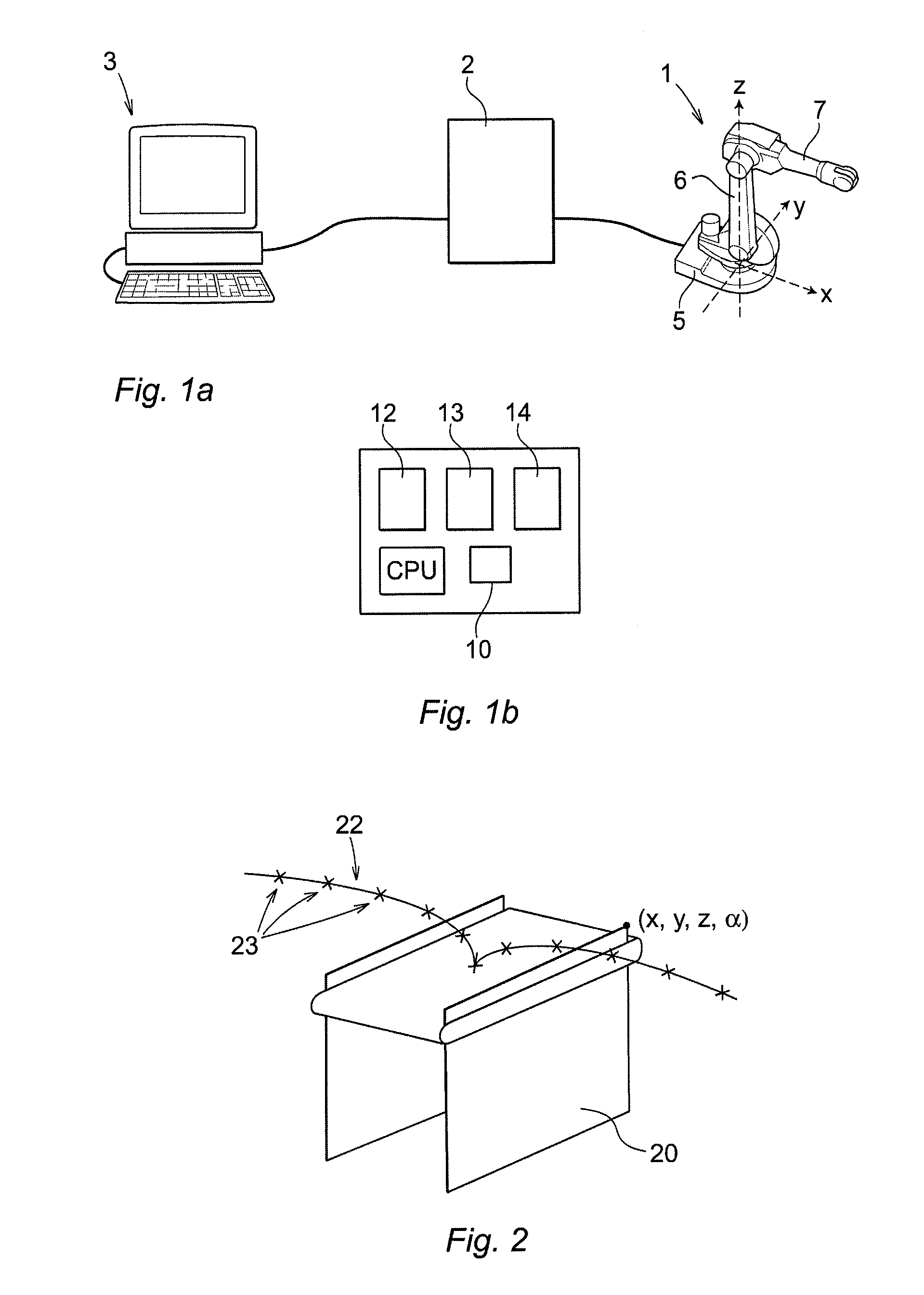
[0044]FIG. 1a shows a robot system including a robot 1, a robot controller 2 and an external computer 3 configured to communicate with the robot controller. The robot includes a plurality of robot parts movable relative to each other. The robot parts are in this case a base frame 5, and robot arms 6,7. The base frame 5 of the robot is arranged in a fixed position relative to the ground. A base coordinate system X, Y, Z is defined relative to the base frame of the robot. The robot is rotatable about the base frame in the Z-direction of the base coordinate system of the robot. The robot controller is configured to control the movements of the robot in accordance with a control program including instruction for moving the robot along paths in order to carry out a sequence of tasks on a plurality of workstations. The external computer includes a processor, such as a central processing unit (CPU), memory for storing programs and data, user input means, such as a keyboard and a mouse, com...


PUM


Abstract

A method for optimizing placement of a plurality of workstations in a workcell including an industrial robot programmed to execute a sequence of tasks on the workstations. Each task contains robot targets to be visited by the robot when executing the task. A preferred region is defined within the reachable range of the robot. Tasks are placed inside or as close as possible to the preferred region using an evaluation criterion and an optimization algorithm. The tasks are assigned to each workstation a position inside or close to the preferred region. A best order of the workstations and a defined order in which the tasks are to be executed are determined. The positions of the workstations are adjusted utilizing an optimization algorithm configured to run the robot program iteratively in order to optimize the placement of the workstations with regard to the robot performance.

Description

FIELD OF THE INVENTION[0001]The present invention relates to a method and a system for optimizing the placement of a plurality of workstations in a workcell including an industrial robot programmed to execute a sequence of tasks on the workstations.[0002]The invention relates to the technology of robot manipulators and automated production applications. The invention refers to a method and system for optimizing the layout of a work cell involving one or more tasks and an industrial robot executing these tasks.PRIOR ART[0003]Robots are usually placed in work cells in order to facilitate the automation of a complex series of actions. The work cell may comprise a number of different workstations and the robot can be programmed to perform different tasks at the different workstations. A workstation is a physical location on which the robot may carry out work. Examples of workstations are injection molding machines, die casting machines, scrap stations for throwing away rejected objects,...

Claims


Application Information

Patent Timeline
Patent Type & Authority Patents(United States)
IPC IPC(8): G06F19/00G05B19/18
CPCG05B19/41885G05B2219/32015G05B2219/32085G05B2219/32301Y02P90/02
Inventor ZHANG, EMILY-DANDANQI, LEVY-LIWEIMURPHY, STEVE
Owner ABB RES LTD
Why Eureka
Try Eureka