Illuminating optical lens for light emitting diode (LED)

a technology of light-emitting diodes and illumination optical lenses, which is applied in the direction of lighting, instruments, lighting and heating apparatus, etc., can solve the problems of increasing the complexity of the package adaptation for efficient heat dissipation, requiring more precise current and heat management, and being relatively expensiv

Active Publication Date: 2013-11-05
CORELED SYST
View PDF29 Cites 32 Cited by
  • Summary
  • Abstract
  • Description
  • Claims
  • Application Information

AI Technical Summary

Benefits of technology

[0011]It is an object of the present invention to provide optical lenses and LED light fixture assemblies for use in various luminaire systems having high optical efficiencies and low manufacturing tolerances.

Problems solved by technology

First, they were used in expensive equipment such as laboratory and electronics test equipment, then later in such appliances as TVs, radios, telephones, calculators, and even watches.
These red LEDs were bright enough only for use as indicators, as the light output was not enough to illuminate an area.
Most LEDs were made in the very common 5 mm T1¾ and 3 mm T1 packages, but with increasing power output, it has become increasingly necessary to shed excess heat in order to maintain reliability, so more complex packages have been adapted for efficient heat dissipation.
However, they are relatively expensive and require more precise current and heat management than traditional light sources.

Method used


Image

  • Illuminating optical lens for light emitting diode (LED)
  • Illuminating optical lens for light emitting diode (LED)
  • Illuminating optical lens for light emitting diode (LED)

Examples


example

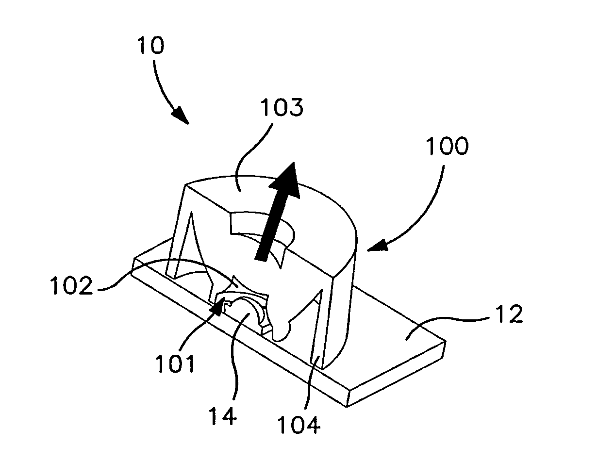
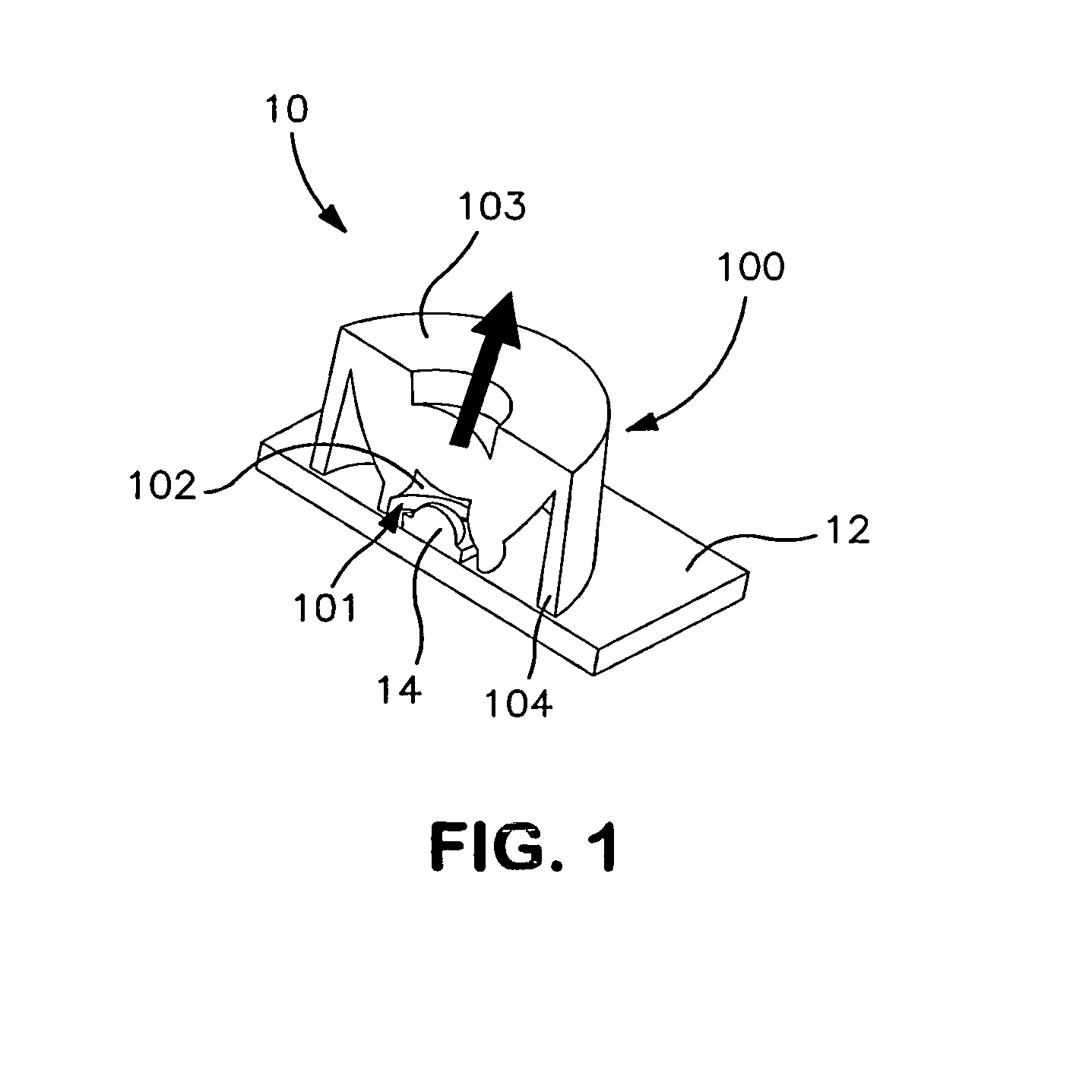
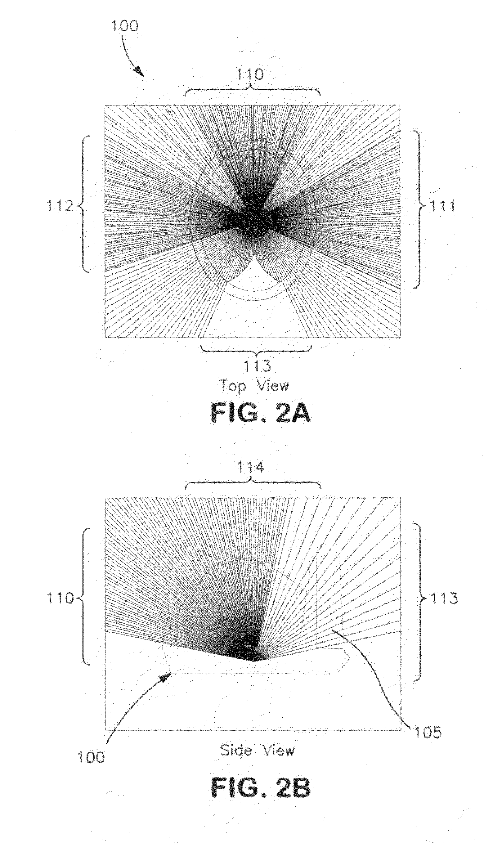
[0060]The following example illustrates the application of the above general design principles (e.g., including Snell's Law and total internal reflection (TIR)) to select a lens geometry having desired light focusing / spreading characteristics, for example when used in combination with a particular LED light source. Simulated light patterns for the lenses illustrated in FIGS. 6A-6D and 7A-7F are shown.

[0061]Lenses and their component surfaces are suitably designed computationally using conventional ray tracing / simulation software (e.g., LIGHTTOOLS software available from Optical Research Associates, Pasadena, Calif.) taking into account the physical properties (e.g., refractive index) of the lens material (e.g., PMMA or other polymer). A design paradigm is selected based on the manner in which the light emanating in generally all directions from a LED light source is desired to be focused / redirected by the lens (e.g., a desired final or far field pattern goal). For example, it may be...


PUM

PropertyMeasurementUnit
refractive indexaaaaaaaaaa
diameteraaaaaaaaaa
diameteraaaaaaaaaa

Abstract

An illuminating optical lens article of manufacture for use with a light emitting diode (LED) mounted on a circuit board has (a) a base portion defining a rim on a plane having a bottom surface around a longitudinal axis for mounting over the LED; (b) an integral refractive outer surface of the lens extending towards the longitudinal axis from the base; (c) an integral refractive inner surface of the lens extending from the base forming a cavity shaped and sized to receive an LED; and optionally (d) a plurality of grooved sections for receiving an adhesive formed on the bottom surface of the base portion. The base is adapted to be mounted on the circuit board onto which the LED is mounted. The integral refractive outer and inner surfaces each define a predetermined geometry adapted to direct and focus light emitting from the LED to a predetermined path.

Description

CROSS-REFERENCE TO RELATED APPLICATION[0001]Priority is claimed to U.S. Provisional Application No. 61 / 277,549, filed Sep. 25, 2009, the disclosure of which is incorporated herein in its entirety.STATEMENT REGARDING FEDERALLY SPONSORED RESEARCH OR DEVELOPMENT[0002]Non-applicableBACKGROUND OF THE INVENTION[0003](1) Field of the Invention[0004]The present disclosure relates to a light emitting diode (LED) lens, lighting systems, and methods of use and manufacturing.[0005](2) Description of Related Art[0006]Early light emitting diode (LED) devices emitted low-intensity red light, but modern LEDs are available across the visible, ultraviolet and infra red wavelengths, with very high brightness. LEDs are based on the semiconductor diode. When the diode is forward biased (switched on), electrons are able to recombine with holes and energy is released in the form of light. This effect is called electroluminescence and the color of the light is determined by the energy gap of the semiconduc...

Claims


Application Information

Patent Timeline
Patent Type & Authority Patents(United States)
IPC IPC(8): F21V3/00F21V5/00
CPCF21S8/088F21V5/04F21V5/08G02B19/0071G02B19/0095G02B19/0028G02B19/0061F21W2111/023F21Y2101/02F21Y2115/10Y10T29/49826
Inventor MALLORY, DEREK S.WELLS, BRIAN C.
Owner CORELED SYST
Why Eureka
Try Eureka