Method for preparing a ferrule assembly

a technology of ferrules and assembly parts, applied in the direction of optics, optical elements, instruments, etc., can solve the problems of inability to form connectors, low yield of satisfactory assemblies, time-consuming and skill-intensive process of cleaving and polishing optical fibers, etc., to avoid the polishing of ferrules and reduce waste

Active Publication Date: 2013-11-05
TYCO ELECTRONICS LOGISTICS AG (CH)
View PDF11 Cites 4 Cited by
  • Summary
  • Abstract
  • Description
  • Claims
  • Application Information

AI Technical Summary

Benefits of technology

[0008]The present invention provides a method for preparing a ferrule assembly for optical coupling that avoids polishing of the ferrule and reduces waste while providing adequate control over fiber end protrusion and / or fiber end co-planarity in the completed ferrule assembly. Unlike prior art methods, the inventive method involves precisely positioning a prepared distal end of the fiber prior to securing the fiber in the ferrule. In one embodiment, the distal end of the fiber is prepared to include a desired end face geometry prior to insertion of the fiber into a ferrule. The method further involves positioning the prepared fiber relative to the ferrule in a precise manner, and then securing the fiber within the ferrule only after the desired fiber position is obtained. Because no post-insertion or post-securing polishing is required, the desired fiber position is retained in the completed ferrule assembly. In another embodiment, the distal end of the fiber is prepared after insertion into the ferrule, and a measuring system such as an interferometer or a machine vision system is used to precisely position the prepared end before securing the fiber in the ferrule.

Problems solved by technology

It is a time-consuming and skill-intensive process to cleave and polish the optical fiber, and polishing must be performed to exacting standards.
No matter the techniques and tools used, cleaving and polishing the fiber end(s) / ferrules often results in a connector that will be unable to form an acceptable optical interconnection, due to improper cleaving, improper polishing technique and / or under- or over-polishing that causes variation from the desired protrusion and / or co-planarity specifications.
This conventional termination process is characterized by a significant amount of defective assemblies and fiber / ferrule / connector waste, and thus a low yield of satisfactory assemblies.

Method used


Image

  • Method for preparing a ferrule assembly
  • Method for preparing a ferrule assembly
  • Method for preparing a ferrule assembly

Examples


Embodiment Construction

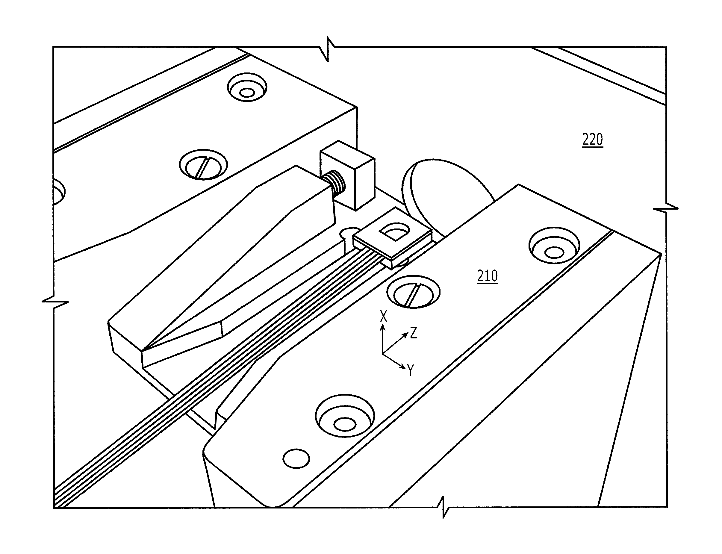
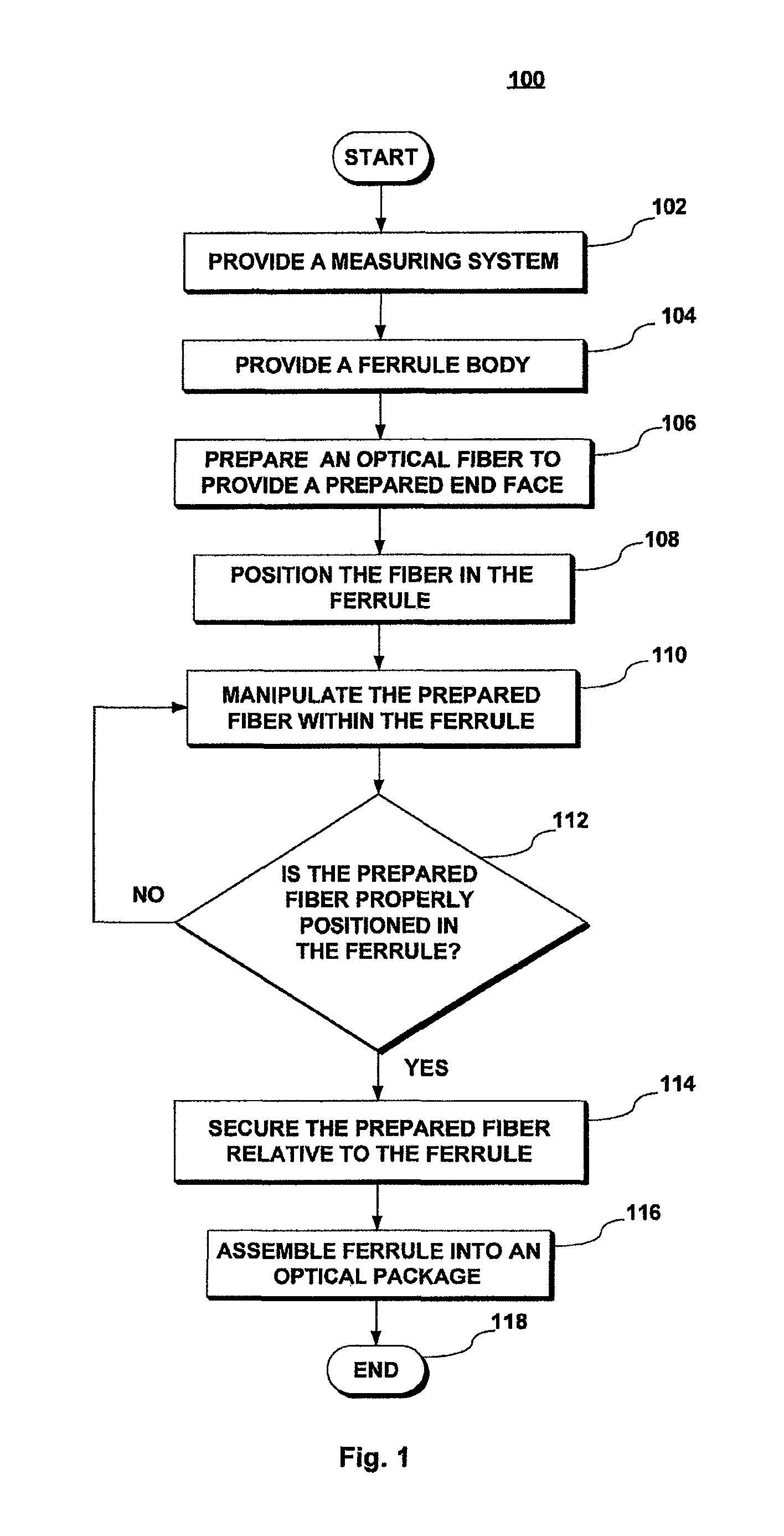
[0018]FIG. 1 shows a flow chart 100 depicting an overview of a preferred method for preparing a ferrule assembly in accordance with the present invention. As used herein, the term “ferrule assembly” refers to a ferrule having one or more fibers terminated in it. The method begins with providing a measuring system capable of measuring distances in the range of approximately −10 to 10 micrometers (e.g., 10 micrometers proximally and distally of a reference point such as the ferrule end face), and providing a suitable ferrule body, as shown at steps 102 and 104. The measuring system may include a conventional non-contact interferometer or a conventional machine vision system, as discussed in greater detail below. The ferrule body has one or more pathways to receive fibers therein. Any desired conventional ferrule body may be used for this purpose, as discussed in greater detail below.

[0019]In the next step 106, one or more fibers are prepared for physical contact optical coupling. More...


PUM

PropertyMeasurementUnit
distanceaaaaaaaaaa
distancesaaaaaaaaaa
distanceaaaaaaaaaa

Abstract

A method for preparing a ferrule assembly avoids polishing while providing adequate control over fiber end protrusion and co-planarity. A distal end of the fiber is prepared before securing the fiber in a ferrule, and before or after inserting the fiber into the ferrule. The prepared fiber is manipulated to provide a desired spatial relationship between the fiber end and the ferrule's end face, and then secured to maintain the desired spatial relationship. Preferably, the fiber end is prepared using a laser cleaving technique to provide a suitable end without abrasive polishing. An interferometer may be used to obtain measurements, during manipulation of the prepared fiber within the ferrule, that indicate whether the prepared fiber is satisfactorily positioned. In accordance with other aspects of the invention, a ferrule assembly prepared in accordance with the method, and a connector or other optical package including such a ferrule assembly are provided.

Description

FIELD OF INVENTION[0001]The present invention relates generally to preparing a ferrule assembly including one or more optical fibers suitable for optical coupling, and, more particularly, to preparing a ferrule assembly without post-insertion polishing, while allowing for control of fiber end protrusion and fiber end co-planarity in the completed ferrule assembly.BACKGROUND[0002]Fiber optic communication systems include optical connectors that join segments of optical fibers. The principal function of an optical fiber connector is to hold a fiber end such that the core of the fiber is axially aligned with the optical path of the fiber component, etc. to which the connector is mated, e.g., so that light from the one fiber is optically coupled to another.[0003]To mate fiber connectors, the end portion of each optical fiber must be mated with the end portion of a corresponding optical fiber. To minimize Fresnel loss, physical contact should be made between the fiber ends. Typically opt...

Claims


Application Information

Patent Timeline
Patent Type & Authority Patents(United States)
IPC IPC(8): G02B6/36
CPCG01B11/02G02B6/3834G02B6/3833G02B6/3843G02B6/3885
Inventor WEBB, JOSHUA L.ROHDE, DOUGLAS HAROLDCORMANY, DAVID WILLIAMGURRERI, MICHAEL LAWRENCE
Owner TYCO ELECTRONICS LOGISTICS AG (CH)
Why Eureka
Try Eureka