
Optical shaping for amplification in a semiconductor optical amplifier

a semiconductor optical amplifier and optical shaping technology, applied in the field of optical communication network systems, to achieve the effect of reducing the deleterious impact of soa fast gain dynamics and efficient optical amplification

Active Publication Date: 2013-11-05
INFINERA CORP
View PDF39 Cites 3 Cited by
  • Summary
  • Abstract
  • Description
  • Claims
  • Application Information

AI Technical Summary

Benefits of technology

This approach reduces waveform distortions and phase noise, enabling more power extraction from SOAs and resulting in a more economical and efficient optical communication system with improved spectral efficiency.

Problems solved by technology

Amplified spontaneous emission conversion occurring in SOAs, which is particularly detrimental to DPSK systems, would have a much smaller impact on systems based on duobinary.

Method used


Image

  • Optical shaping for amplification in a semiconductor optical amplifier
  • Optical shaping for amplification in a semiconductor optical amplifier
  • Optical shaping for amplification in a semiconductor optical amplifier

Examples


Embodiment Construction

[0033]The following description is set forth for purpose of explanation in order to provide an understanding of the invention. However, it is apparent that one skilled in the art will recognize that embodiments of the present invention, some of which are described below, may be incorporated into a number of different computing systems and devices. The embodiments of the present invention may be present in hardware, software or firmware. Structures and devices shown below in block diagram are illustrative of exemplary embodiments of the invention and are meant to avoid obscuring the invention. Furthermore, connections between components within the figures are not intended to be limited to direct connections. Rather, data between these components may be modified, re-formatted or otherwise changed by intermediary components.

[0034]Reference in the specification to “one embodiment”, “in one embodiment” or “an embodiment” etc. means that a particular feature, structure, characteristic, or...


PUM


Abstract

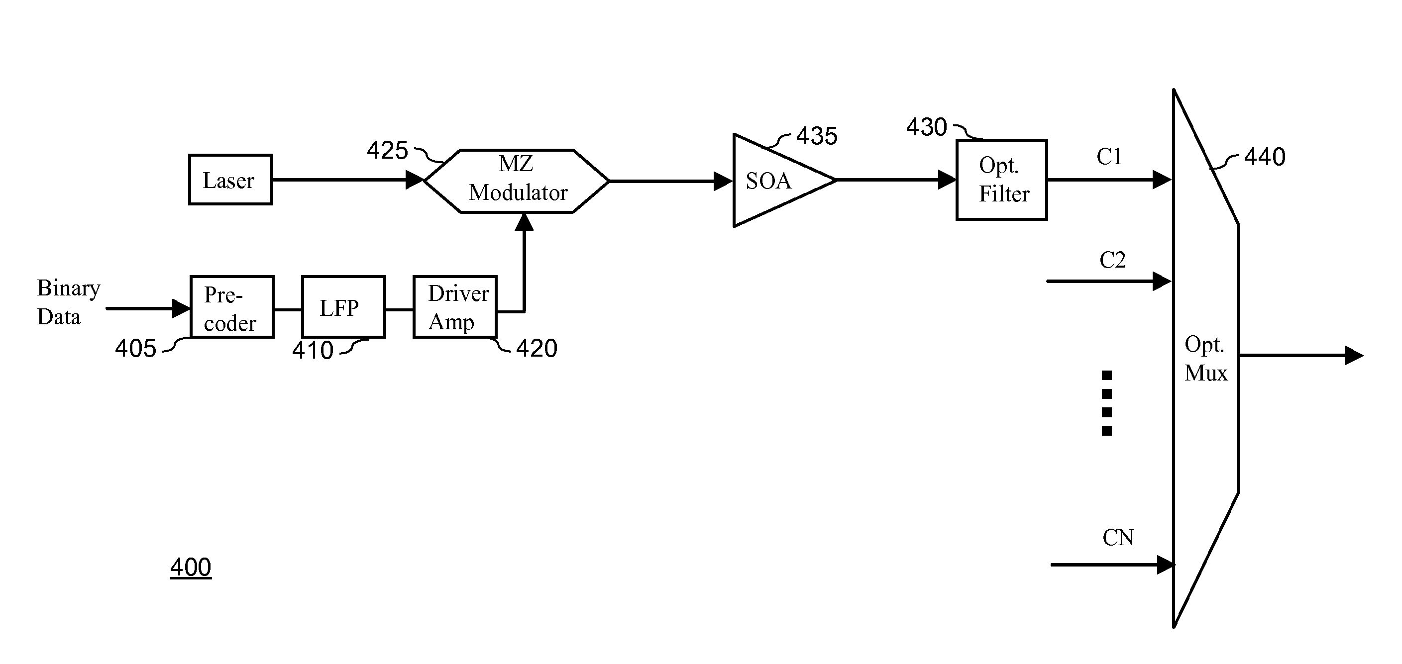
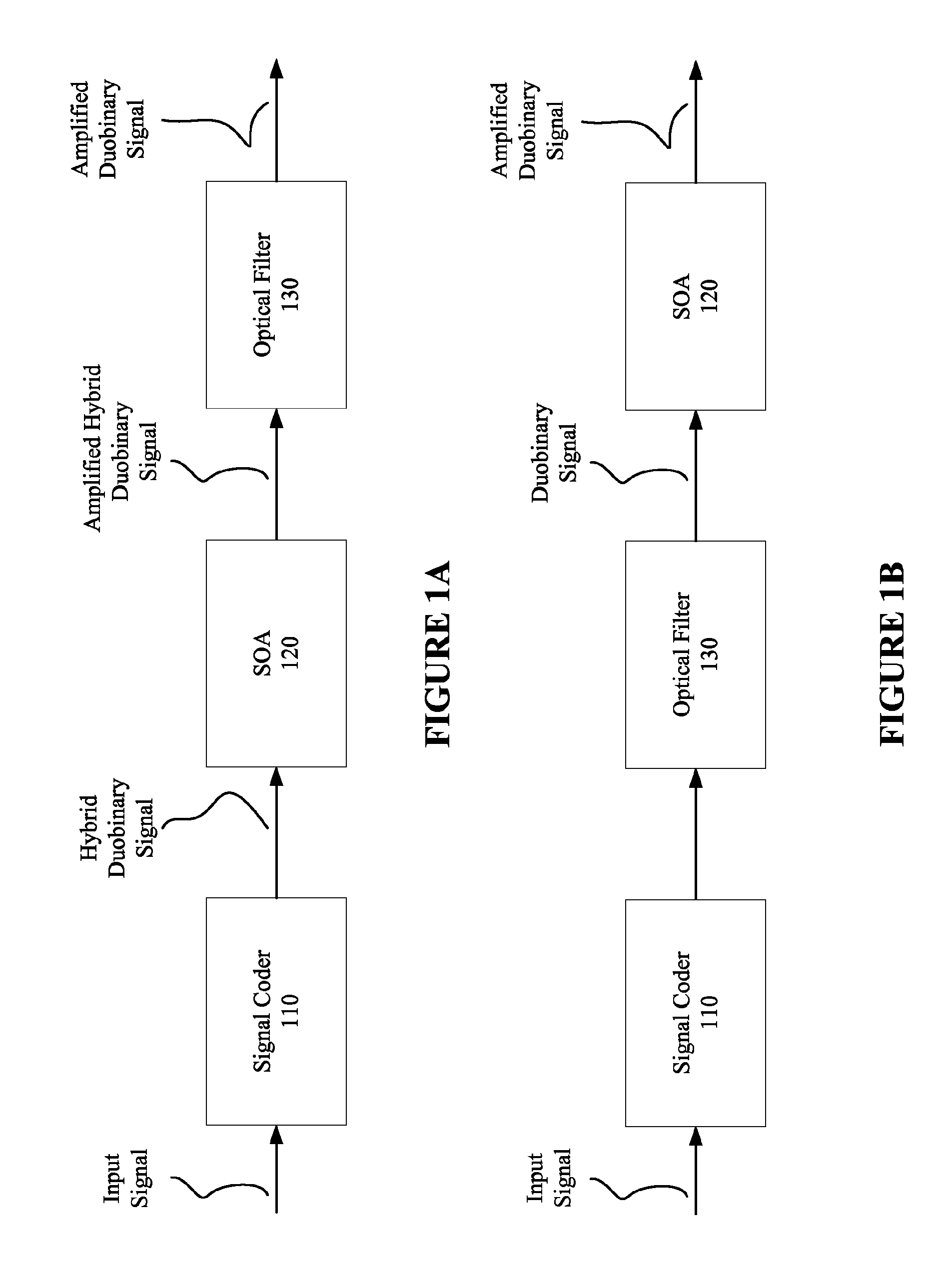
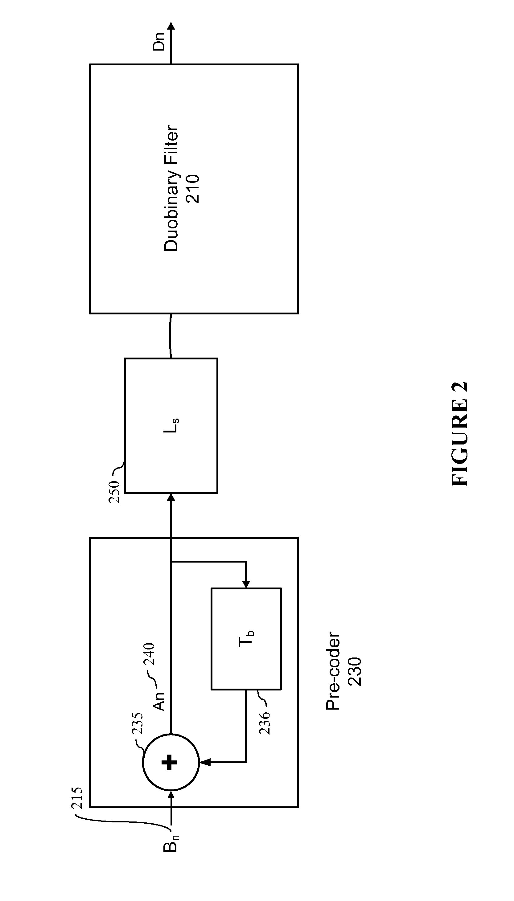
The present invention provides a system, apparatus, and method for efficient optical amplification and transmission of a data-encoded optical signal within a networking device, such as a transmitter or receiver. In various embodiments of the invention, an optical duobinary signal or hybrid duobinary signal is generated and shaped in preparation for amplification of the optical signal by an SOA. The deleterious impact of SOA fast gain dynamics may be reduced by taking advantage of characteristics of a duobinary or hybrid duobinary signal (e.g., a relatively lower pulse amplitude and no phase encoded data) and shaping the optical duobinary pulse (e.g., smoothing amplitude swings within the signal and spectral compression).

Description

BACKGROUND[0001]A. Technical Field[0002]The present invention relates generally to optical communication network systems, and more particularly, to optical duobinary transmitters and receivers configured for fiber-optic communication systems.[0003]B. Background of the Invention[0004]The importance of high-speed optical networks is understood by one of skill in the art. High-speed networking devices typically operate at the core of a network and allow a network provider to transport large amounts of data. In order to meet the widely differing bandwidth demands of various communication applications, several communication technologies are being used, many having unique characteristics and advantages.[0005]Wavelength Division Multiplexed (hereinafter, “WDM”) transport networks allow multiple, information-bearing wavelengths to be communicated within a single fiber. The multiplexing of optical wavelengths within a single WDM signal allows a service provider to vary the amount of bandwidt...

Claims


Application Information

Patent Timeline
Patent Type & Authority Patents(United States)
IPC IPC(8): H04B10/00
CPCH04B10/5167H04B10/675H04B10/2914H04B10/588H04J14/0221
Inventor LYUBOMIRSKY, ILYA
Owner INFINERA CORP
Learn More