Sample plate for fluid analysis in a refinery process

a technology of fluid analysis and sample plate, which is applied in the direction of chemical library, combinational chemistry, component separation, etc., to achieve the effect of constant quality crude oil blend

Active Publication Date: 2013-11-26
ALIXIUM DEVICES LTD
View PDF18 Cites 8 Cited by
  • Summary
  • Abstract
  • Description
  • Claims
  • Application Information

AI Technical Summary

Benefits of technology

[0070]Because of the rapid analysis obtainable from the equipment set of the present invention, analyses can be obtained more often and / or can be used for process optimisation. For example, the equipment set may be used at a refinery and regular analyses can be performed on blends of refinery feedstocks, such as blends of crude oils, produced (from two or more sources available) at the refinery, to ensure optimum configuration of the refinery for the blend. Further the equipment set may be used to verify consistency and / or quality of feedstocks on arrival at a refinery or blending station and / or may be used to provide on-line or at-line determination of feedstock quality and property data for input to blending and process refinery optimisation models.
[0071]Where the equipment set of the present invention is used at the “well-head” on a drilling site, a number of sets may be operated at different well-heads which use a common transport mechanism, for example a common pipeline, to provide analysis of the crude oil from each well. Analysis of the individual crude oils and appropriate scheduling may allow more optimum composition of the final crude oil blend. In addition, by repeated analysis of the crude oils from different well-heads, changes in the individual crude oils with time can be used to predict the effects on the produced crude oil blend, or influence the blending to maintain a constant quality crude oil blend.

Problems solved by technology

Traditionally, this has been a time-consuming analysis, requiring a relatively large volume of material and taking 1-2 weeks to produce a full set of analysis (assay) data.

Method used


Image

  • Sample plate for fluid analysis in a refinery process
  • Sample plate for fluid analysis in a refinery process
  • Sample plate for fluid analysis in a refinery process

Examples


Embodiment Construction

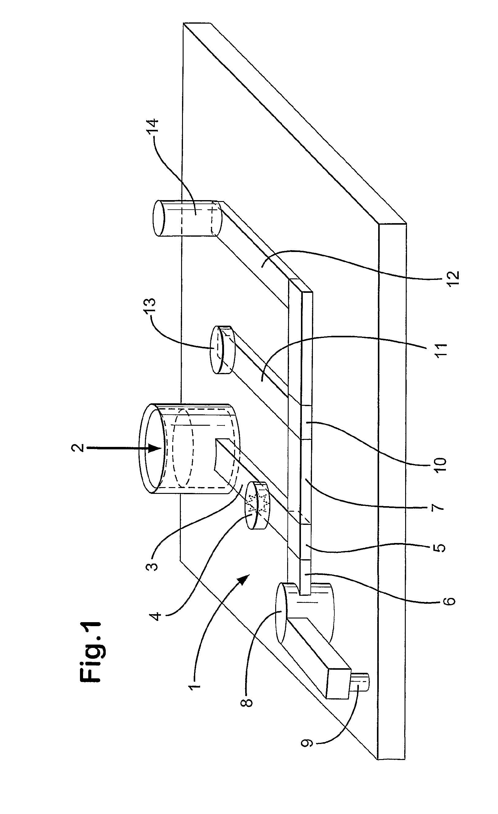
[0081]Referring now to FIG. 1, a sample plate illustrated generally as 1 comprises a receiver 2 for a fluid to be analysed, in this case crude oil. A first fluidic channel 3 transfers crude oil from receiver 2 to a gear pump 4, by which the oil may be metered. The crude oil stream is then sent to a first micro valve 5 which controls the flow permitting the creation of first and second streams 6 and 7. First stream 6 passes to a head space generation device 8 and thence to an inlet 9 for a micro gas chromatography device. Second stream 7 passes to a second micro valve 10 which controls the flow permitting the creation of third and fourth streams 11 and 12. Third stream 11 is passed to an acidity sensor 13, while fourth stream 12 is passed to a sample cell 14 for a micro NIR spectrometer.

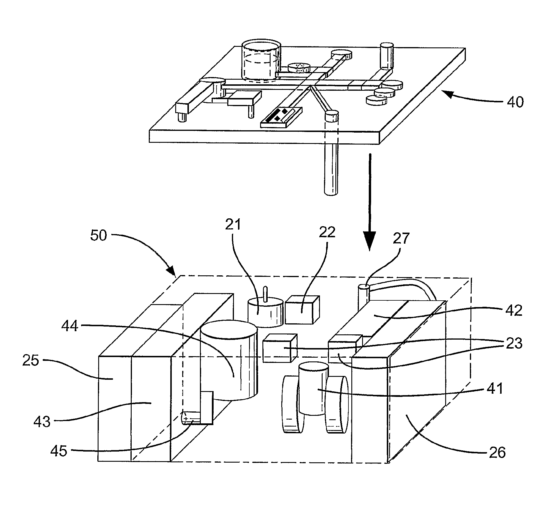
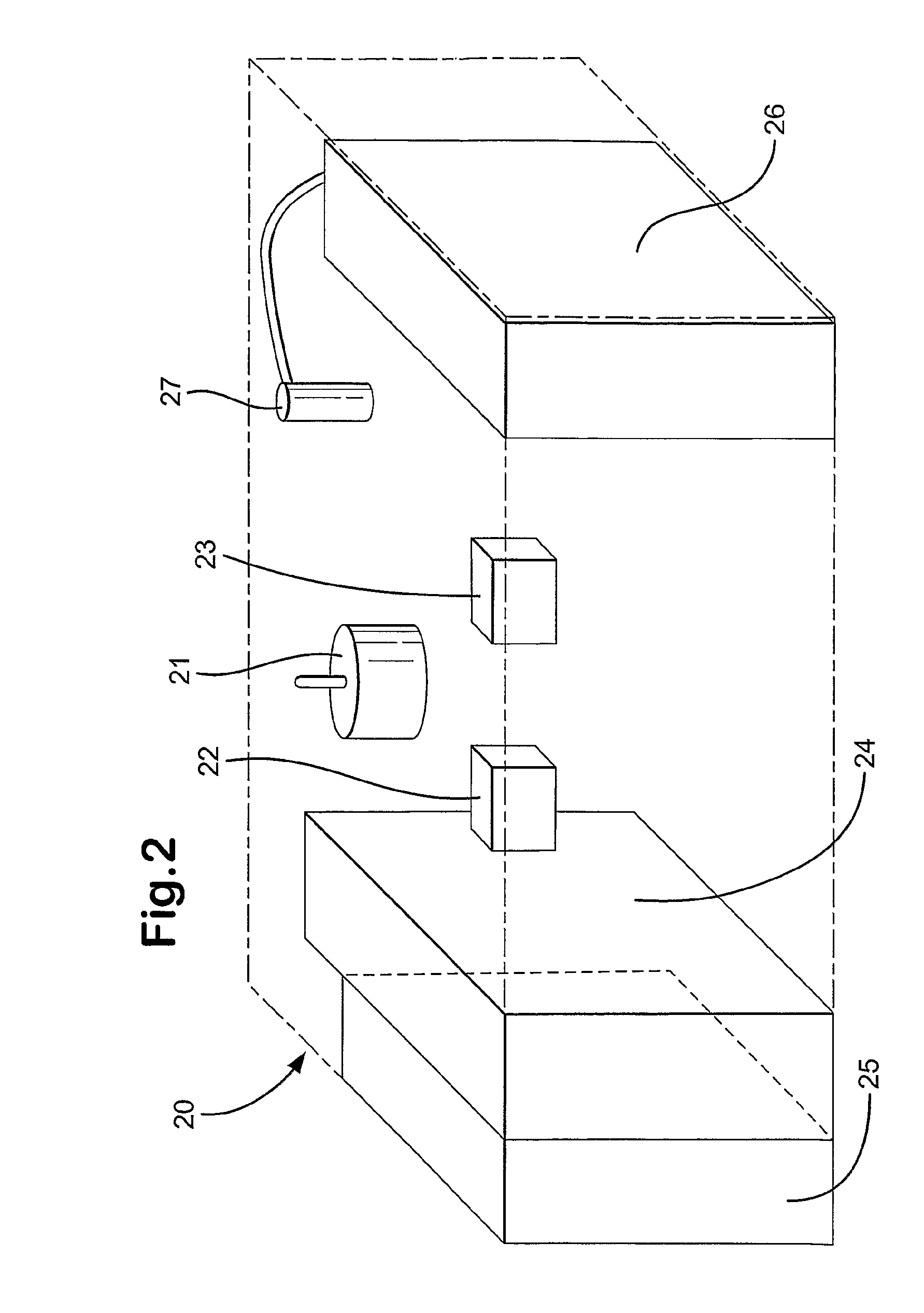
[0082]The sample plate of FIG. 1 is adapted to be used with a portable apparatus illustrated schematically in FIG. 2. The portable apparatus shown generally at 20 comprises a micro pump driver 21 adap...


PUM

PropertyMeasurementUnit
total weightaaaaaaaaaa
boiling pointaaaaaaaaaa

Abstract

Equipment for analyzing a fluid selected from a hydrocarbon fluid, a refinery feedstock, a refinery intermediate, a product of a refinery process, or a component or reaction product thereof, having a portable apparatus containing at least two different analytical devices, each device being able to analyze the fluid. A sample plate is provided in association with the portable apparatus which has a receiver for a fluid to be analyzed, at least two fluidic channels, at least one sensor capable of responding to a physical or chemical property of the fluid, and/or at least one sample cell, and at least one additional fluidic channel for transferring a portion of the fluid or a component or reaction product thereof from the receiver to the at least one sensor and/or sample cell.

Description

[0001]This application is the U.S. national phase of International Application No. PCT / GB2007 / 000127 filed 17 Jan. 2007 which designated the U.S. and claims priority to European Patent Application No. 06250495.6 filed 30 Jan. 2006, the entire contents of each of which are hereby incorporated by reference.[0002]This invention relates to a sample plate for use with a portable apparatus for analysis of a fluid, for example a refinery feedstock, a refinery intermediate, or a product of a refinery process.BACKGROUND OF THE INVENTION[0003]Feedstock analysis, for example crude oil assay, is an important analysis that is typically performed before feedstocks are purchased for or refined in an oil refinery. Typically, an oil refinery will refine a large number of different feedstocks, including different crude oils, and blends of crude oils, each of which may differ in a number of important properties. In order to ascertain the optimum conditions for refining of each feedstock and to evaluat...

Claims


Application Information

Patent Timeline
Patent Type & Authority Patents(United States)
IPC IPC(8): G01N33/22
CPCB01L3/502715G01N33/2823G01N35/1095B01L9/527B01L2200/025B01L2200/027B01L2200/10B01L2300/0645B01L2300/0816B01L2400/0487G01N33/2876G01N27/624Y10T436/21
Inventor HODGES, MICHAEL GRAHAM
Owner ALIXIUM DEVICES LTD
Why Eureka
Try Eureka