
Method and circuit for trimming an internal oscillator of a USB device according to a counting number between a first and second clock count value

a technology of internal oscillators and counting numbers, which is applied in the direction of generating/distributing signals, instruments, pulse techniques, etc., can solve the problems of not meeting the regulations, rc oscillators generating frequency with potential errors, and inability to allow frequency sources to be integrated into the integrated circuit (ic) of usb devices, etc., to achieve accurate trimming, simplify the trimming circuit, and reduce the effect of trimming tim

Inactive Publication Date: 2013-11-26
ELAN MICROELECTRONICS CORPORATION
View PDF19 Cites 6 Cited by
  • Summary
  • Abstract
  • Description
  • Claims
  • Application Information

AI Technical Summary

Benefits of technology

[0006]An object of the present invention is to provide a method and circuit for trimming an internal oscillator of a USB device with a shorter trimming time.
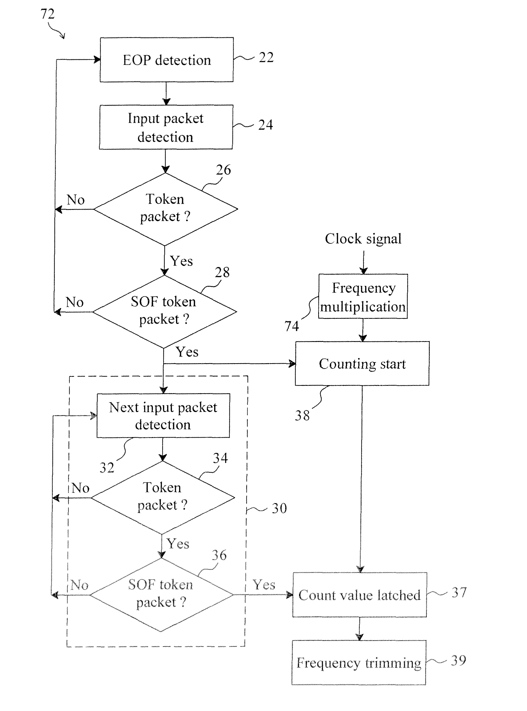
[0010]By identifying a token packet and then accurately detecting a SOF token packet, the clock frequency of a USB device can be accurately trimmed in a single step, thereby reducing the trimming time and simplifying the trimming circuit.

Problems solved by technology

However, this approach is impossible to allow the frequency source integrated into the integrated circuit (IC) of the USB device.
However, due to process variation, the RC oscillator generates frequency with a potential error up to ±25%, failing to meet the regulations of the USB driver protocols.
However, as this two-step trimming process (i.e., coarse-tuning followed by fine-tuning) relies on the first data frame in the data stream of the USB host for coarse-tuning and the second and third data frames in the data stream of the USB host for fine-tuning, not only is the trimming time relatively long (about the time period of three data frames), but also is required a relatively complicated circuit.

Method used


Image

  • Method and circuit for trimming an internal oscillator of a USB device according to a counting number between a first and second clock count value
  • Method and circuit for trimming an internal oscillator of a USB device according to a counting number between a first and second clock count value
  • Method and circuit for trimming an internal oscillator of a USB device according to a counting number between a first and second clock count value

Examples


Embodiment Construction

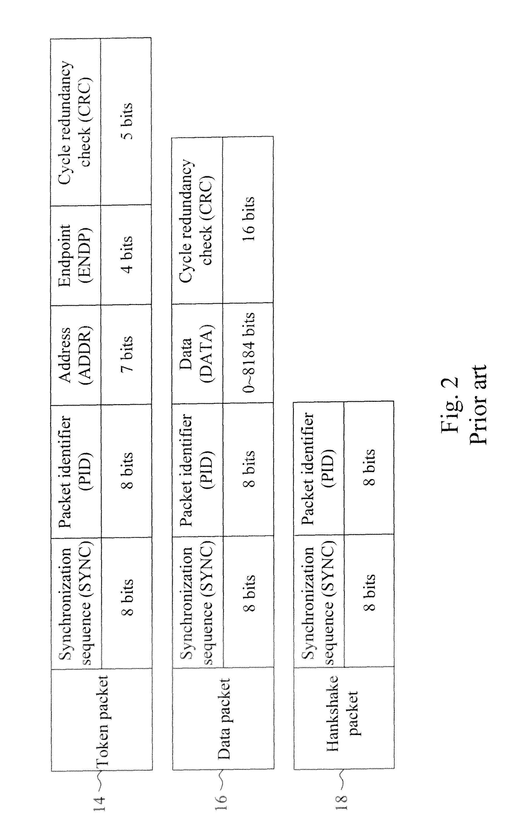
[0019]According to a first embodiment of the present invention, FIGS. 3 and 4 are flowchart 20 and circuit diagram 40, respectively. Referring to FIGS. 1 to 4, in step 22, a detector 42 detects an end of packet (EOP) in a data stream from a USB host, which is between the end of a packet and the beginning of the next packet in the data stream, to generate a reset signal R to initialize counters 46 and 48, thereby resetting the count value of the counters 46 and 48 to zero. In step 24, a detector 44 detects an input packet in the data stream of the USB host. In step 26, the detector 44 identifies whether or not the input packet is a token packet according to the synchronization sequences (SYNC) of the input packet. If the input packet is not a token packet, the process goes back to step 22; otherwise, the process goes to step 28. In step 28, the detector 44 identifies whether or not the input packet is a SOF token packet according to the packet identifier (PID) of the input packet. If...


PUM


Abstract

A circuit and method for trimming an internal oscillator of a USB device that generates a clock signal as a frequency source of the USB device detect an end of packet from an input data stream to initialize a counter, identify a token packet in the data stream to detect a start of frame token packet for the counter to carry out clock counting on the clock signal to thereby obtain a count value, and compare the count value with a reference value to determine a trimming code for trimming a clock frequency of the internal oscillator.

Description

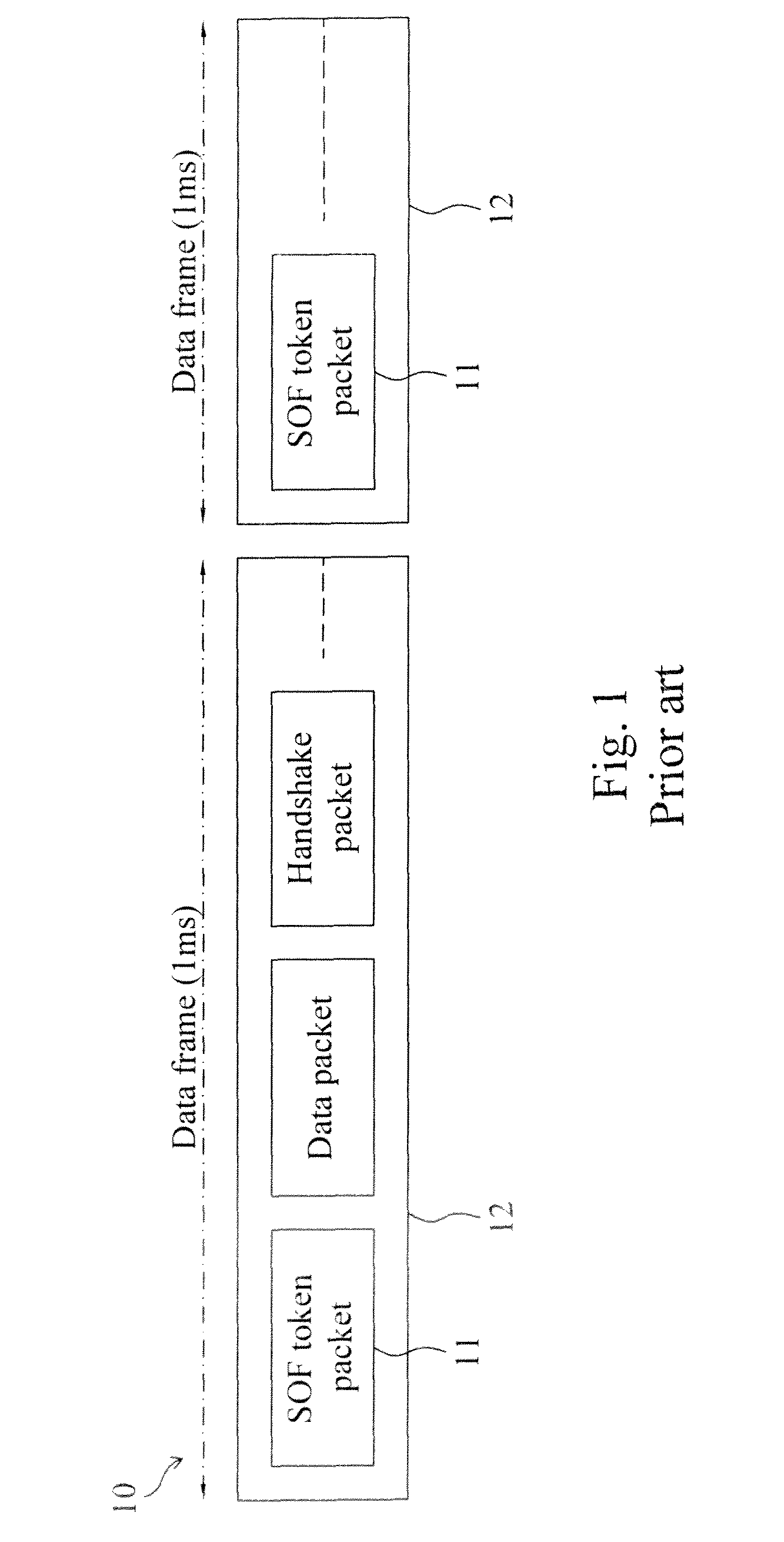
FIELD OF THE INVENTION[0001]The present invention is related generally to a universal serial bus (USB) device and, more particularly, to a method and circuit for trimming an internal oscillator of a USB device.BACKGROUND OF THE INVENTION[0002]In USB 2.0 and 1.1 driver protocols, there are strict regulations for the operation frequencies of low-speed, full-speed, and high-speed communication interfaces between USB hosts and USB devices for satisfying various applications. For example, the data rate specification of data streams in low-speed USB hosts is 1.5 MHz±1.5%, for keyboards, mice and so on, in full-speed USB hosts is 12 MHz±0.25%, for audio applications and microphones, and in high-speed hosts is 480 MHz±0.05%, for video applications and imaging. Conventionally, as a frequency source of a USB device, a crystal oscillator or a resonant oscillator, optionally with a digital phase lock loop (PLL), is used to generate an accurate frequency signal. However, this approach is impossi...

Claims


Application Information

Patent Timeline
Patent Type & Authority Patents(United States)
IPC IPC(8): G06F1/00H04L25/64G06F1/12
CPCH04L7/0331H04L7/042
Inventor CHIANG, TSUNG-YINWANG, CHUN-CHIWU, PO-HAOTANG, CHUN-AN
Owner ELAN MICROELECTRONICS CORPORATION
Learn More