Sub sea hybrid valve actuator system and method

a hybrid valve actuator and actuator technology, applied in the field of actuator control system, can solve the problems of less than desirable reliability, mechanical complexity, and extensive instrumentation in non-retrievable components, and achieve the effect of great robustness and reliability

Active Publication Date: 2013-12-03
VETCO GRAY SCANDINAVIA
View PDF33 Cites 18 Cited by
  • Summary
  • Abstract
  • Description
  • Claims
  • Application Information

AI Technical Summary

Benefits of technology

[0033]The present invention also facilitates protection of motor and pump by detection of end-of stroke position.
[0036]One advantageous feature of the valve actuator system of the present invention is that it can easily be expanded to serve fail-to-last position actuation, typically for a manifold or choke application, by simply reversing direction of rotation of the electrical motor, removing the fail safe spring and designing the piston / cylinder for bidirectional action. This assumes full reversibility of the pump, usually the case for a gear pump, not always the case for a piston pump. In the case of a piston machine it would be beneficial to use a motor as pump as they are usually designed for true bidirectional operation both in pump and motor mode.

Problems solved by technology

Both approaches have merits and both also have certain limitations.
The former approach tends to involve mechanical complexity and extensive instrumentation in non-retrievable components (i.e. for example integrated with an XMT module) and large dimensions.
The latter approach tends to involve several hydraulic components demonstrated over many years to have less than desirable reliability in a sub sea context, e.g. DCV pilot valves requiring high fluid cleanliness for reliable operation, pressure relief valves and hydraulic accumulators.
The latter, if in the form of nitrogen (N2) charged bladder design, are prone to leakage over time, which is the reason they are normally carried on easily retrievable modules.
In deep water N2 charged accumulators are also inefficient.
In the form of mechanical spring charged designs accumulators are bulky and unsuitable to be part of an actuator located on e.g. an XMT.
The full range of valves normally used in a mini SHPU dedicated to control of a single actuator are basically considered sensitive to particulate contamination and thus undesirable.

Method used


Image

  • Sub sea hybrid valve actuator system and method
  • Sub sea hybrid valve actuator system and method
  • Sub sea hybrid valve actuator system and method

Examples


Embodiment Construction

[0081]In the following preferred embodiments of the invention will be described. A complete list of references is attached to the end of the detailed description.

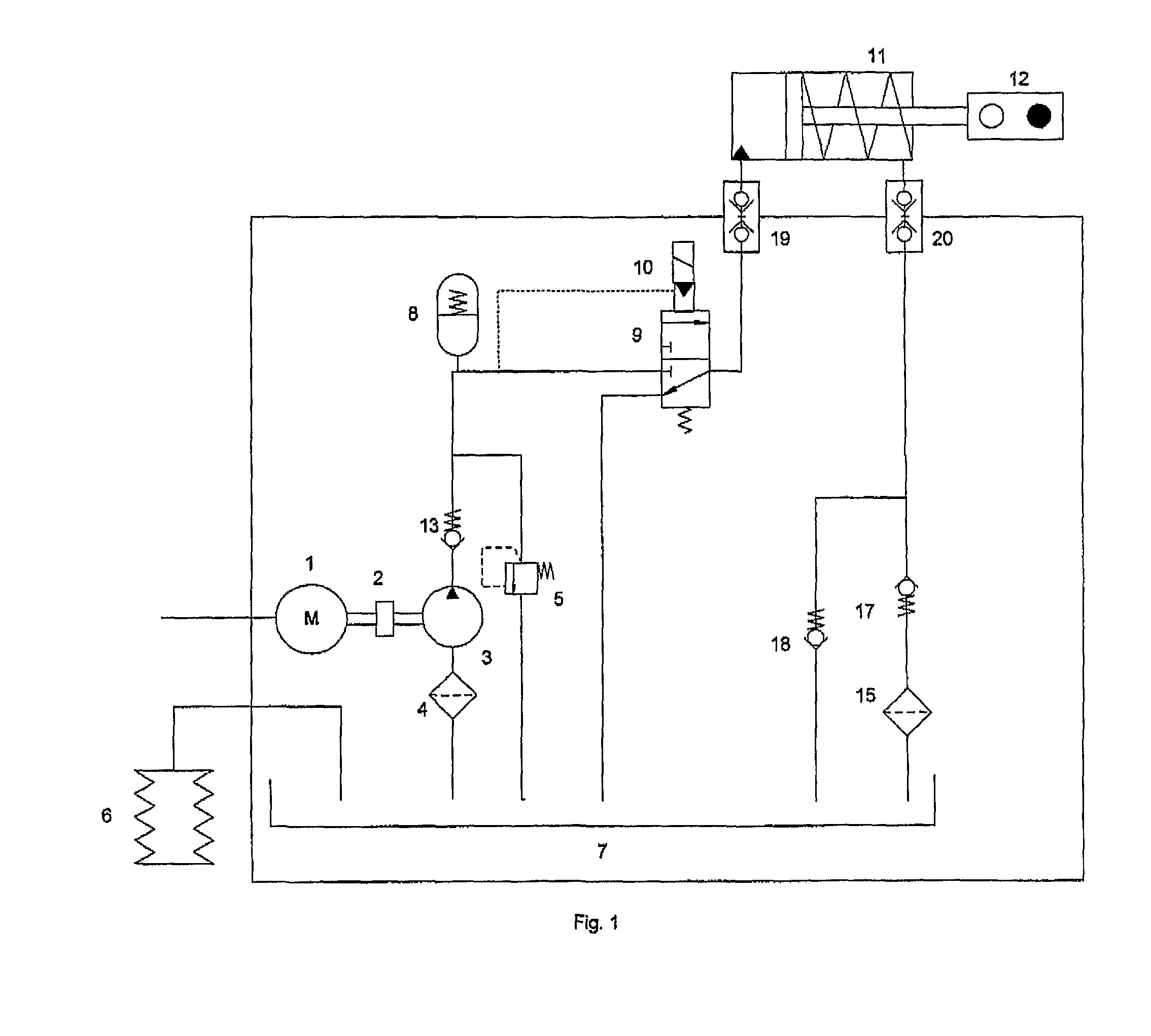
[0082]With reference to FIG. 1, the prior art hydraulic circuit discussed in the background typically comprises the following components: an electric motor 1, flexible coupling 2, hydraulic pump 3, pump inlet strainer or filter 4, pressure relief valve 5, volume compensator 6, oil reservoir 7, hydraulic accumulator 8, control valve 9, pilot valve 10, hydraulic cylinder 11 with spring biased piston, gate valve 12, return filter 15, check valves 13, 17, 18 and hydraulic couplings 19 and 20.

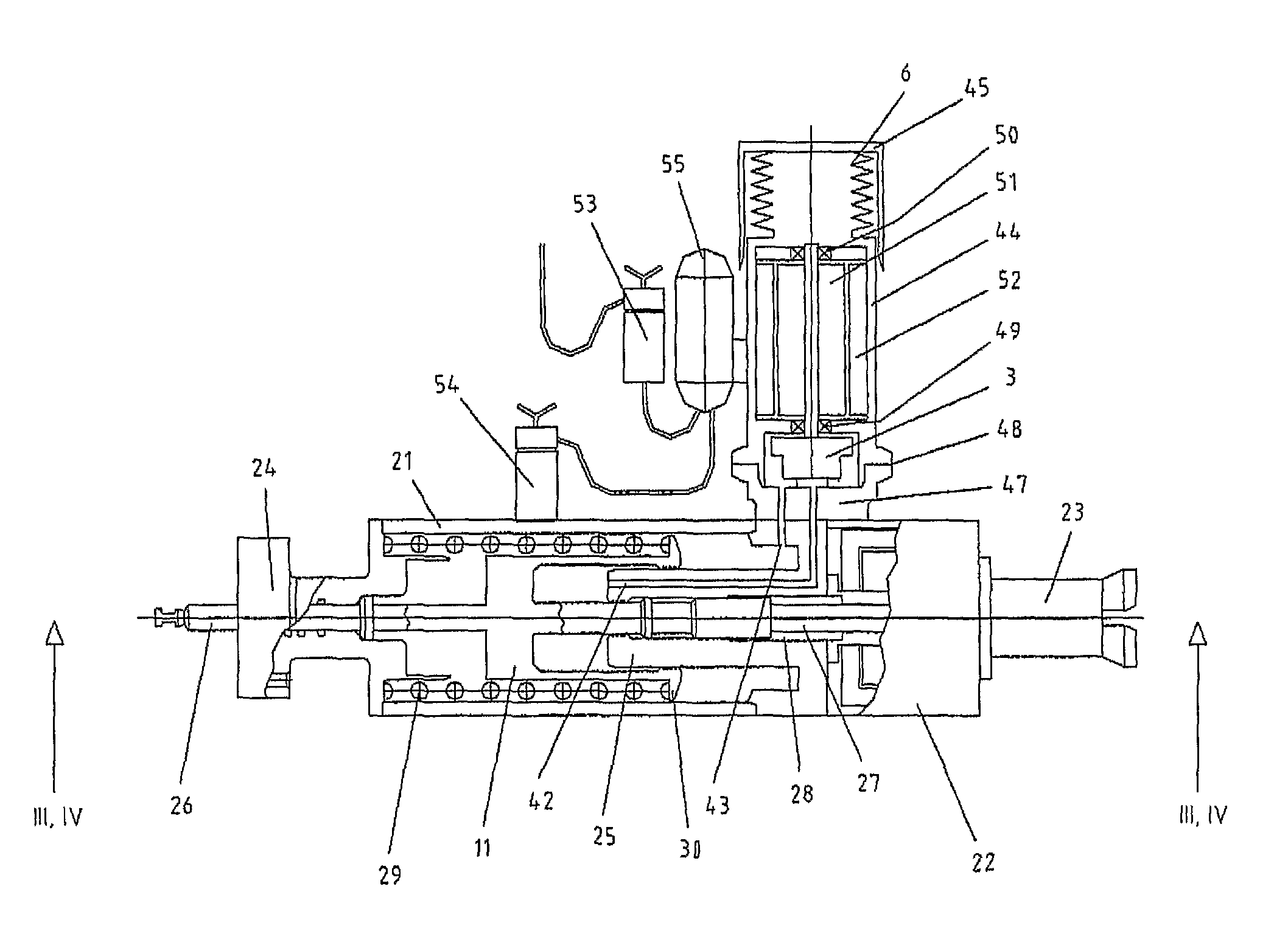
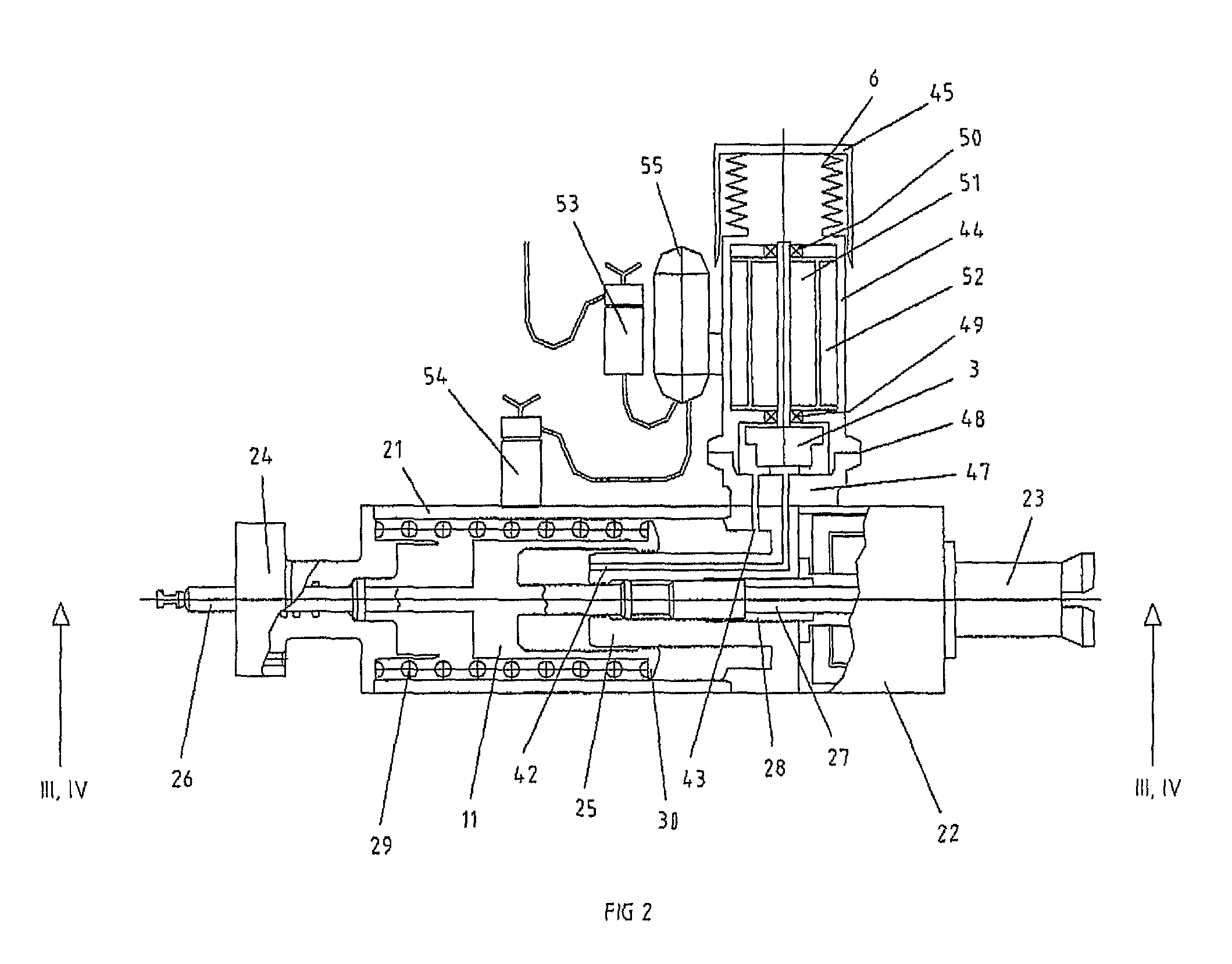
[0083]The simplified system of the present invention is correspondingly illustrated in FIG. 6. With reference to FIGS. 6 and 7, the motor 1 drives the pump 3 via flexible coupling 2 to create a pressure downstream the pump 3 as soon as the flow out of the pump is met with a restriction to flow. The least restriction to flow is represented b...


PUM


Abstract

A sub sea valve actuator system including a piston and cylinder assembly and a return spring arranged in an actuator housing, a hydraulic pump and electric motor assembly associated with the piston and cylinder assembly, and hydraulic flow lines for hydraulic medium driving the piston and cylinder in relative displacement against a force of the return spring. The valve actuator system includes a detector configured to detect an end-of-stroke position of the piston and cylinder assembly. The detector includes at least one of: a motor current monitoring circuit unit, a hydraulic medium pressure sensor unit, a position sensor unit, and a linear variable differential transformer unit. An electromechanical arresting mechanism is arranged to be energized for releasably arresting the return spring in a compressed state in result of the detected end-of-stroke position. A method for operation of a sub sea valve actuator system by which an end-of-stroke position for a piston and cylinder assembly in a sub sea valve actuator system can be determined.

Description

CROSS-REFERENCE TO RELATED APPLICATIONS[0001]This application claims priority to Norwegian patent application 20082217 filed 14 May 2008 and is the national phase under 35 U.S.C. §371 of PCT / IB2009 / 005567 filed 12 May 2009.TECHNICAL FIELD OF THE INVENTION[0002]The present invention relates generally to an actuator control system useful in sub sea production of hydrocarbons. It relates specifically to a sub sea valve actuator system and a method to achieve a simple and robust control system at low cost and low qualification effort. The actuator system is compatible with the concept of sub sea electric production control architecture.BACKGROUND AND PRIOR ART[0003]In the following background discussion as well as in the disclosure of the present invention, the following abbreviations will be frequently used:[0004]BL brush-less[0005]DC direct current[0006]DCV directional control valve[0007]EH MUX electro-hydraulic multiplexer[0008]ESD emergency shut down[0009]I / O input / output[0010]LVDT ...

Claims


Application Information

Patent Timeline
Patent Type & Authority Patents(United States)
IPC IPC(8): F16K31/122
CPCE21B33/0355E21B34/04Y10T137/7723Y10T137/0396Y10T137/8242Y10T137/0318Y10T137/0379
Inventor GRIMSETH, TOMBORCHGREVINK, CHRISTIANFLIDH, JONPETTERSEN, JAN OLAV
Owner VETCO GRAY SCANDINAVIA
Why Eureka
Try Eureka