
Control circuit for switching power supply

a control circuit and power supply technology, applied in the direction of electric variable regulation, process and machine control, instruments, etc., can solve the problems of excessive output voltage increase and adverse effect on circuit element reliability

Active Publication Date: 2013-12-03
ROHM CO LTD
View PDF7 Cites 7 Cited by
  • Summary
  • Abstract
  • Description
  • Claims
  • Application Information

AI Technical Summary

Benefits of technology

The patent describes a method for controlling the charging of a capacitor in a control circuit. By intermittently charging the capacitor and using it to generate a soft-start voltage, the control circuit can achieve a smooth transition from soft-start control to feedback control. The soft-start voltage has a low rate of change over time, even if the capacitor has a small capacitance. This allows the capacitor to be built into the control circuit. The technical effects of this method include reducing the effective charge current and achieving a smooth transition between soft-start control and feedback control.

Problems solved by technology

If there is a sudden increase in the output voltage, in some cases, this leads to an inrush current occurring in the output capacitor, or leads to overshoot or ringing occurring in the output voltage, which excessively raise the output voltage.
In some cases, this leads to adverse effects on the reliability of the circuit elements.

Method used


Image

  • Control circuit for switching power supply
  • Control circuit for switching power supply
  • Control circuit for switching power supply

Examples


Embodiment Construction

[0037]The invention will now be described based on preferred embodiments which do not intend to limit the scope of the present invention but exemplify the invention. All of the features and the combinations thereof described in the embodiment are not necessarily essential to the invention.

[0038]In the present specification, the state represented by the phrase “the member A is connected to the member B” includes a state in which the member A is indirectly connected to the member B via another member that does not substantially affect the electric connection therebetween, or that does not damage the functions or effects of the connection therebetween, in addition to a state in which the member A is physically and directly connected to the member B.

[0039]Similarly, the state represented by the phrase “the member C is provided between the member A and the member B” includes a state in which the member A is indirectly connected to the member C, or the member B is indirectly connected to ...


PUM


Abstract

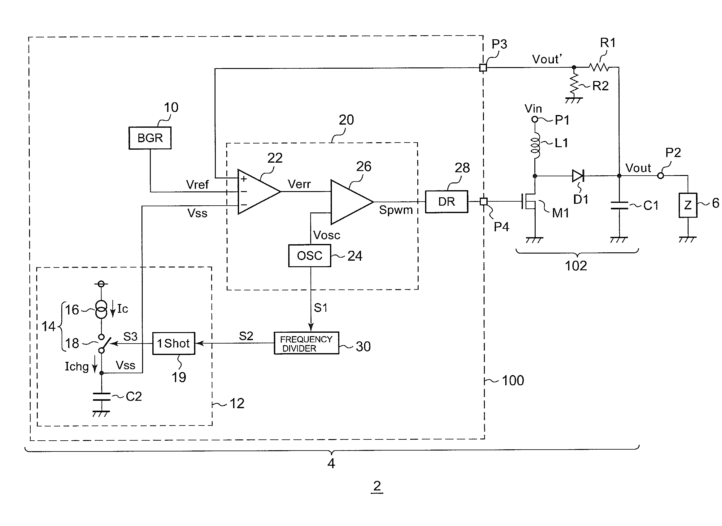
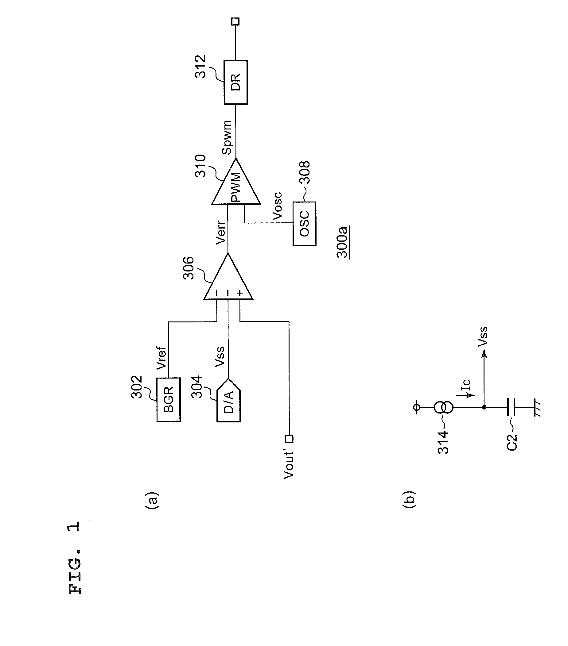
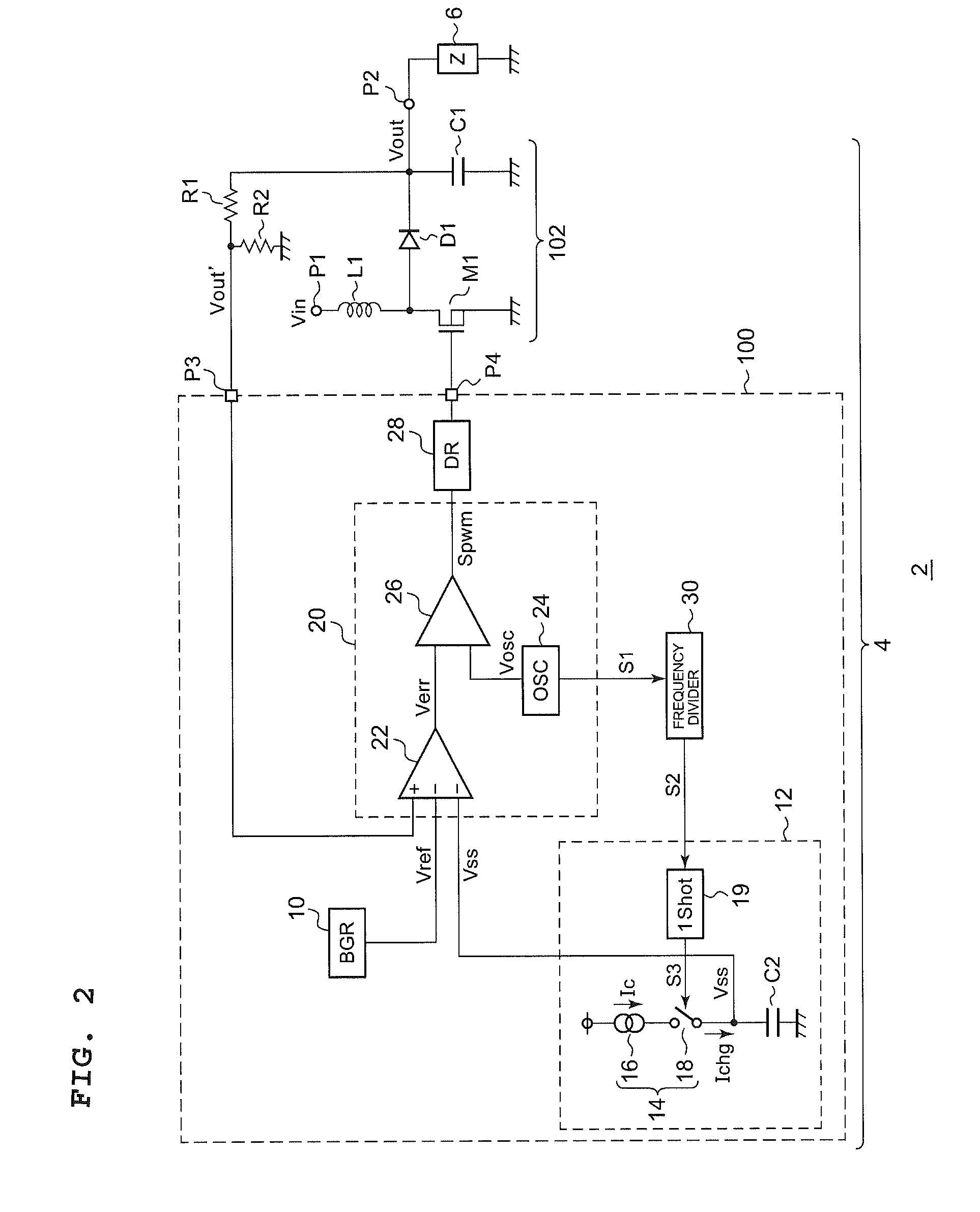
A soft-start circuit generates a soft-start voltage Vss having a voltage level that rises over time. A pulse width modulator generates a PWM signal having a duty ratio adjusted such that a feedback voltage Vout′ that corresponds to the output voltage Vout of the switching power supply matches the soft-start voltage Vss. A driver circuit controls a switching element according to the PWM signal. A capacitor is arranged such that one terminal thereof is set to a fixed electric potential. A current source generates a charge current that flows intermittently in synchronization with the PWM signal so as to charge the capacitor. The soft-start circuit outputs, as the soft-start voltage Vss, a voltage that occurs at the capacitor.

Description

BACKGROUND OF THE INVENTION[0001]1. Field of the Invention[0002]The present invention relates to a switching power supply, and particularly to a soft-start technique for gradually raising the output voltage of the switching power supply.[0003]2. Description of the Related Art[0004]In order to convert a DC voltage having a given voltage level to a DC voltage having a different voltage level, a switching regulator (DC / DC converter) is employed. Such a switching regulator includes a switching element, a rectifier element, an inductor, and an output capacitor. The switching regulator is configured to stabilize the output voltage to a desired voltage level by adjusting the duty ratio of the on / off operation of the switching element.[0005]When starting up the switching regulator, there is a need to raise the output voltage from a 0 V state, i.e., a state in which the amount of charge stored in the output capacitor is zero, to a state in which it reaches a target value. If there is a sudde...

Claims


Application Information

Patent Timeline
Patent Type & Authority Patents(United States)
IPC IPC(8): H05B41/36G05F1/00G05F1/10
CPCH02M1/36H05B33/0815H02M3/156Y02B20/347H05B45/38Y02B20/30
Inventor UCHIMOTO, DAISUKEKIKUCHI, HIROKIINOUE, NAOKI
Owner ROHM CO LTD
Learn More