Comparator circuit with current mirror

a technology of comparator circuit and current mirror, which is applied in the direction of pulse circuit, pulse technique, instant pulse delivery arrangement, etc., can solve the problems of increasing current consumption, difficulty in suppressing a rise in current consumption, and increasing current consumption of circuits for maintaining a constant current, so as to suppress an increase in bias current, reduce current consumption, and eliminate the effect of bias curren

Active Publication Date: 2013-12-03
FUJI ELECTRIC CO LTD
View PDF12 Cites 2 Cited by
  • Summary
  • Abstract
  • Description
  • Claims
  • Application Information

AI Technical Summary

Benefits of technology

[0020]An object of the invention is to provide a comparator circuit that can achieve a reduction in current consumption with a simple configuration, and moreover, can suppress an increase in current consumption accompanying a rise in power source voltage.
[0028]According to the comparator circuit of the invention, as the bias current flowing through the differential circuit is determined by the current flowing through the resistor (the tail resistor), the current flowing through the tail resistor is determined by the first input voltage, and the first input voltage is generated based on the voltage of the first power source, it is possible to eliminate the effect on the bias current of a fluctuation in the voltage of the second power source. That is, it is possible to suppress an increase in the bias current caused by a rise in the power source voltage. For this reason, in comparison with JP-A-2002-217691 and the heretofore known comparator circuit shown in FIG. 8, it is possible to realize a further reduction in current consumption.

Problems solved by technology

However, when the power source voltage is increased, it is difficult to suppress a rise in the current consumption.
Although a configuration making the current value of the current source 2 shown in FIG. 1 of JP-A-2002-217691 a constant current that does not depend on the power source voltage is not impossible, the current consumption of a circuit for maintaining a constant current increases when increasing the power source voltage, and it is inevitable that the overall configuration is such that the current consumption increases when the power source voltage increases.

Method used


Image

  • Comparator circuit with current mirror
  • Comparator circuit with current mirror
  • Comparator circuit with current mirror

Examples


Embodiment Construction

[0038]Hereafter, a detailed description will be given of an embodiment of the invention.

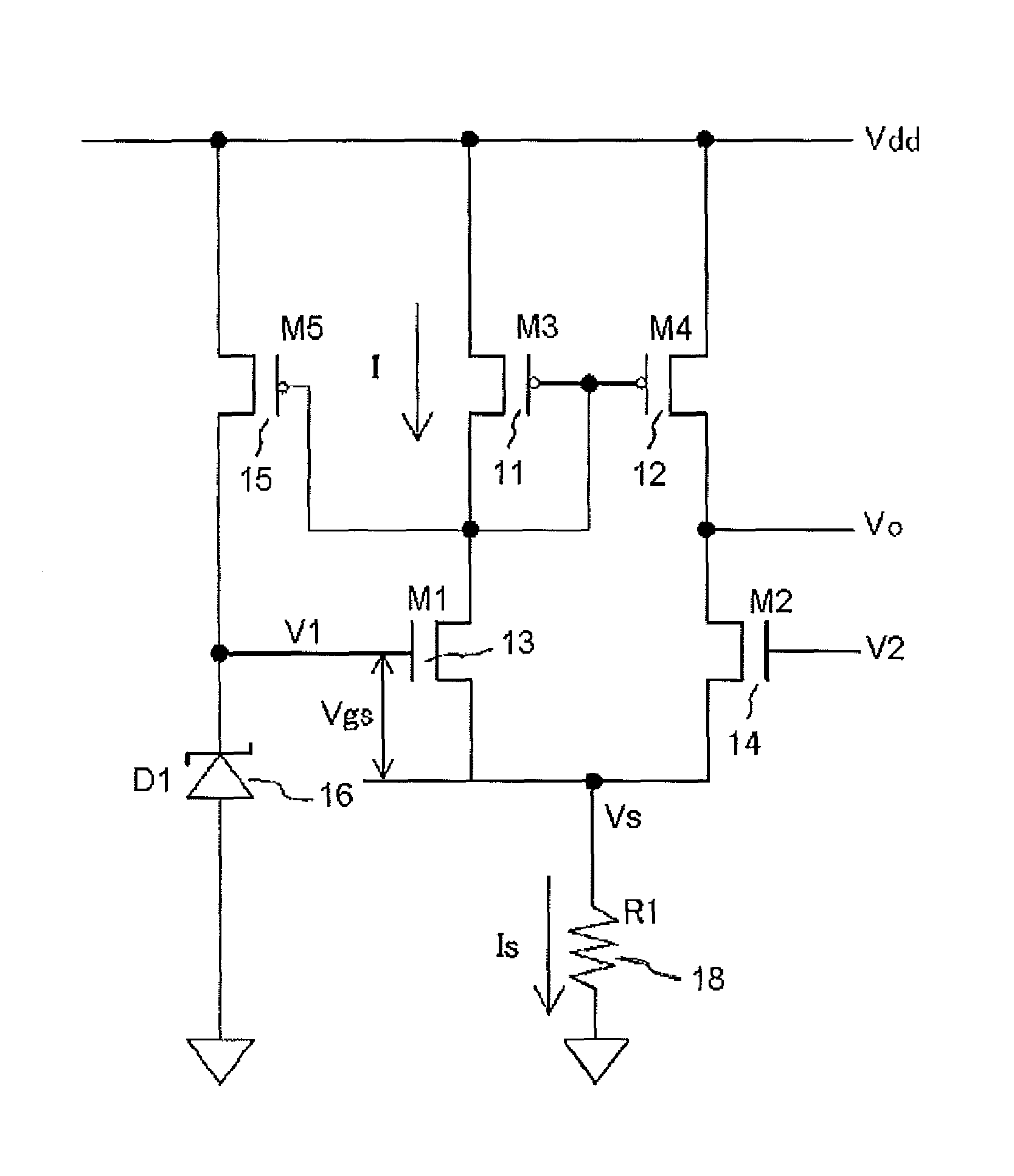
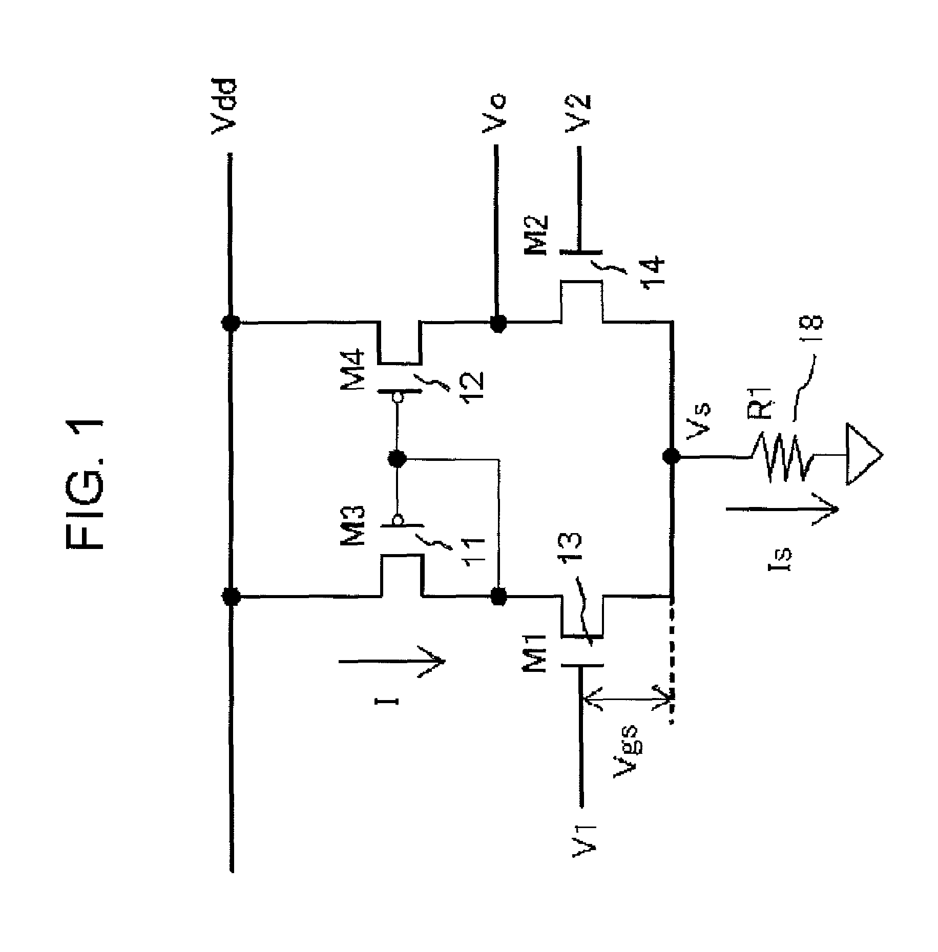
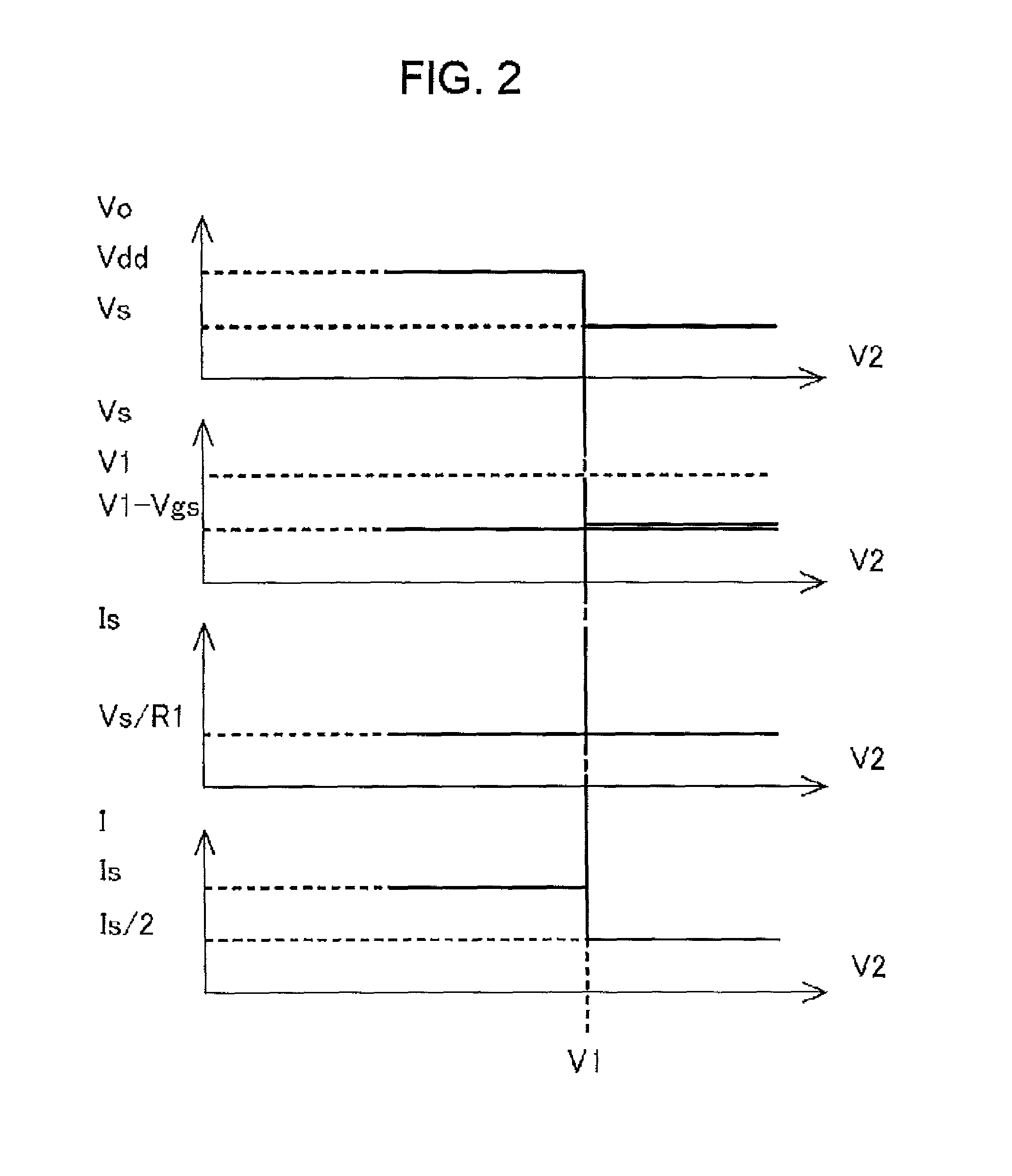
[0039]FIG. 1 is a diagram showing a configuration principle of a comparator circuit according to an embodiment of the invention. FIG. 2 is a diagram showing a waveform in each portion of the comparator circuit shown in FIG. 1 before and after an inversion action. However, the scales of the vertical axis and horizontal axis in FIG. 2 are made different. FIG. 3 is a diagram showing a configuration wherein a reference voltage generator circuit is added to the comparator circuit shown in FIG. 1. Hereafter, a p-channel MOSFET (Metal Oxide Semiconductor Field Effect Transistor) will be abbreviated as PMOSFET, and an n-channel MOSFET as NMOSFET.

[0040]A description will be given of actions of the comparator circuit of the invention, using the configuration principle of the comparator circuit according to the embodiment of the invention shown in FIG. 1. FIG. 1 is for illustrating the configuration princip...


PUM


Abstract

A comparator circuit can achieve a reduction in current consumption with a simple configuration, and can suppress an increase in current consumption accompanying a rise in power source voltage. A current mirror circuit is connected to a power source, and gates of MOSFETs of the circuit are interconnected. An input signal is applied to a gate of an NMOSFET of the circuit. By determining the value of the signal with a constant voltage device, the voltage across a tail resistor is constant, even in the event that the power source voltage and the input signal change.

Description

CROSS-REFERENCE TO RELATED APPLICATION[0001]This application claims priority under 35 U.S.C. §119 from Japanese Patent Application No. 2010-129351, filed on Jun. 4, 2010, the entirety of which is incorporated herein by reference.BACKGROUND OF THE INVENTION[0002]1. Technical Field[0003]The present invention relates to a comparator circuit used in a semiconductor integrated circuit.[0004]2. Related Art[0005]There are many cases in which a circuit that detects voltage level is necessary in a semiconductor integrated circuit, and a comparator circuit is used when configuring the voltage detector circuit. Also, in recent years, there has been a strong demand for a reduction in current consumption in circuits, and a further reduction in current consumption is being sought in comparator circuits too.[0006]FIG. 8 is a diagram showing a configuration of a heretofore known comparator circuit. Hereafter, a p-channel MOSFET (Metal Oxide Semiconductor Field Effect Transistor) will be abbreviated...

Claims


Application Information

Patent Timeline
Patent Type & Authority Patents(United States)
IPC IPC(8): H03K5/153
CPCH03K5/2472
Inventor NISHIJIMA, KENICHIYAMADA, KOUHEI
Owner FUJI ELECTRIC CO LTD
Why Eureka
Try Eureka