Power generating device and electronic component

a power generating device and electronic component technology, applied in piezoelectric/electrostrictive/magnetostrictive devices, piezoelectric/electrostriction/magnetostriction machines, electrical equipment, etc., can solve the problems of limited acquisition voltage and difficulty in reducing and achieve the effect of not increasing the size of the power generating devi

Active Publication Date: 2013-12-10
SEIKO EPSON CORP
View PDF21 Cites 3 Cited by
  • Summary
  • Abstract
  • Description
  • Claims
  • Application Information

AI Technical Summary

Benefits of technology

[0009]In the above-described power generating device, since the piezoelectric member is repeatedly transformed. As a result, in the piezoelectric member, positive and negative electric charge is generated based on the piezoelectric effect. In addition, the amount of generation of the electric charge increases as the amount of transformation of the piezoelectric member increases. When the magnitude of the amount of transformation is the maximum (in other words, when the transformation direction is switched), the piezoelectric member is connected to the inductor. Since the piezoelectric member can be regarded as a capacitor in the sense of an electric circuit, by connecting the piezoelectric member to the inductor, a resonance circuit is formed. Then, the electric charges generated in the piezoelectric member flow into the inductor. Since the piezoelectric member and the inductor configures a resonance circuit, the current flowing into the inductor overshoots and flows into the piezoelectric member from the opposite terminal. This period (that is, a period until the electric charge started to flow from one terminal of the piezoelectric member flows into the piezoelectric material again from the other terminal disposed on the opposite side through the inductor) is a half of the resonance period of the resonance circuit that is formed by the piezoelectric member and the inductor. Accordingly, when the piezoelectric member and the inductor are connected at the timing at which the transformation direction of the piezoelectric member is switched, and thereafter, the inductor is cut off from the piezoelectric member at the timing at which a time corresponding to a half of the resonance period elapses, the arrangement of positive and negative charge generated inside the piezoelectric member before the connection between the piezoelectric member and the inductor can be reversed. From the state, this time, when the piezoelectric member is transformed in the opposite direction, the electric charge generated based on the piezoelectric effect can be accumulated inside the piezoelectric member. As a result, the electric charge generated by repeatedly transforming the piezoelectric member can be effectively accumulated inside the piezoelectric member. In addition, as the electric charge is accumulated inside the piezoelectric member, the voltage between the terminals increases. Accordingly, a voltage that is higher than a voltage generated due to electric polarization of the piezoelectric material can be generated without separately arranging a booster circuit. Therefore, a small-size power generating device having excellent efficiency can be acquired.
[0013]When the transformation direction of the piezoelectric member is switched, there is no current flowing through the rectifier circuit from the piezoelectric member. Accordingly, by connecting the switch so as to connect the piezoelectric member and the inductor to each other when no current flows to the rectifier circuit from the piezoelectric member, the switch can be connected at appropriate timing with high accuracy. As a result, since the piezoelectric member and the inductor can be connected when the electric charge generated by the piezoelectric member becomes the maximum, the electric charge generated in the piezoelectric material can be efficiently taken out, whereby power can be efficiently generated.

Problems solved by technology

However, according to the proposed general techniques, there is a problem that the acquired voltage is limited to the level of a voltage that is generated in accordance with electric polarization of the piezoelectric material.
Accordingly, in most cases, a separate booster circuit is necessary, and there is a problem that it is difficult to decrease the size of the power generating device.

Method used


Image

  • Power generating device and electronic component
  • Power generating device and electronic component
  • Power generating device and electronic component

Examples


Embodiment Construction

[0023]Hereinafter, in order to clarify the content of the invention, embodiments will be described in the following order.[0024]A. Structure of Power Generating Device[0025]B. Operation of Power Generating Device[0026]C. Operating Principle of Power Generating Device[0027]D. Switch Switching Timing[0028]E. Modified Examples

A. Structure of Power Generating Device

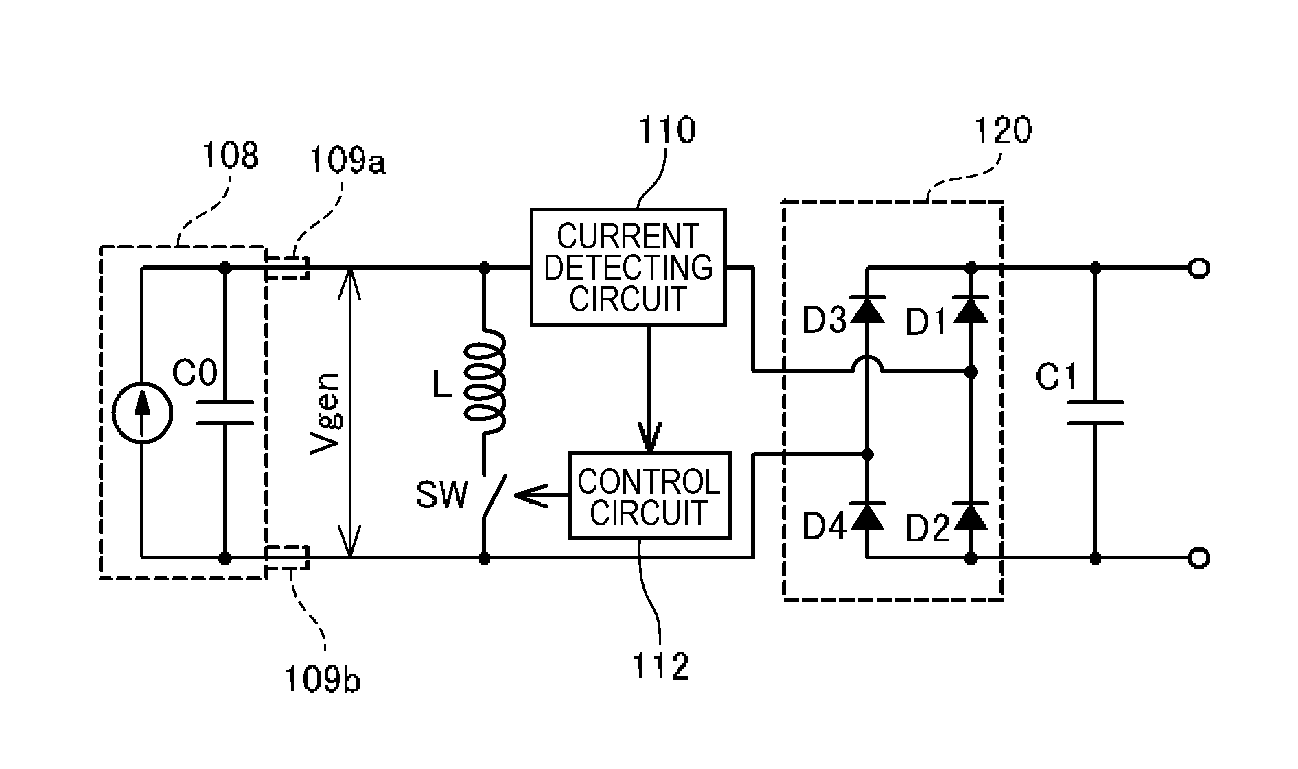
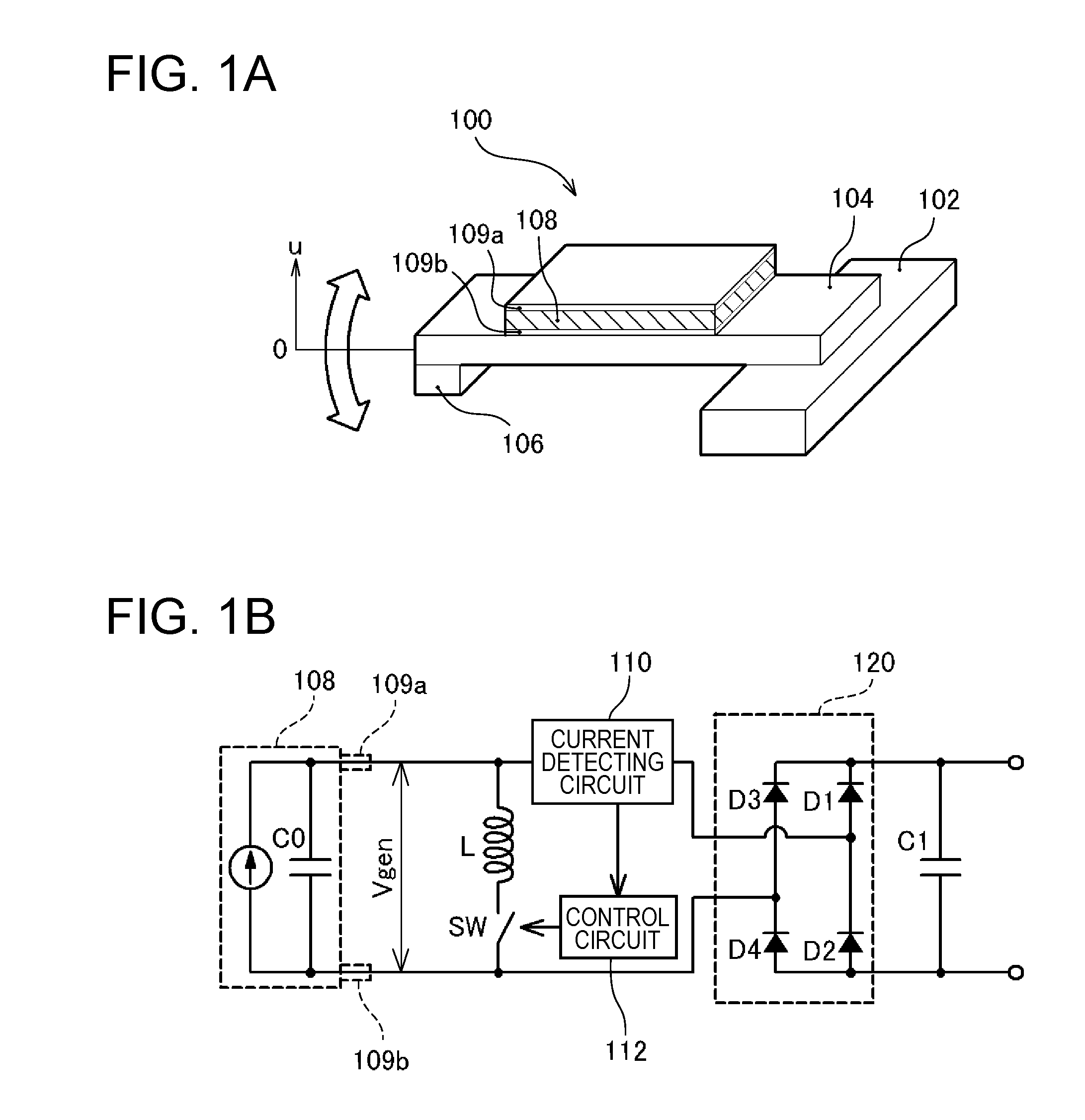
[0029]FIGS. 1A and 1B are explanatory diagrams illustrating the structure of a power generating device 100 according to this embodiment. FIG. 1A shows the mechanical structure of the power generating device 100, and FIG. 1B shows the electrical configuration thereof. As the mechanical structure of the power generating device 100 according to this embodiment, a structure is formed in which a crossbeam 104 having a spindle 106 disposed at the tip end is fixed to a support end 102 on the base end side. On the surface of the crossbeam 104, a piezoelectric member 108 that is formed from a piezoelectric material such as lead zircon...


PUM


Abstract

A power generating device includes: a piezoelectric member that is formed from a piezoelectric material; one pair of electrodes that are installed to the piezoelectric member; a transformation unit that repeatedly transforms the piezoelectric member; an inductor that is installed between the one pair of electrodes and configures a resonance circuit together with a capacitive component of the piezoelectric member; a switch that is connected to the inductor in series; and a switch control unit that connects the switch when a transformation direction of the piezoelectric member is switched, and cuts off the switch when a time corresponding to a half period of a resonance period of the resonance circuit elapses.

Description

BACKGROUND[0001]1. Technical Field[0002]The present invention relates to a power generating device that derives electric energy from an electric charge when a piezoelectric material such as a piezoelectric device is transformed by an external force.[0003]2. Related Art[0004]When a piezoelectric material such as lead zirconate titanate (PZT), crystal (SiO2), or zinc oxide (ZnO) is transformed by an external force, electric polarization is caused inside the material, and positive and negative electric charge appears on the surface. Such a phenomenon is called a piezoelectric effect. A method of generating power is proposed in which, by using such a property of the piezoelectric material, a cantilever is vibrated so as to repeatedly weight the piezoelectric material, and an electric charge generated on the surface of the piezoelectric material is derived as electricity.[0005]For example, by vibrating a metal cantilever which has a spindle arranged at its tip end and to which a thin pla...

Claims


Application Information

Patent Timeline
Patent Type & Authority Patents(United States)
IPC IPC(8): H01L41/08
CPCH02N2/181H10N30/306
Inventor TABATA, KUNIOYOSHINO, HIROYUKIIDE, NORITAKAOSHIMA, ATSUSHI
Owner SEIKO EPSON CORP
Why Eureka
Try Eureka