Tubular supporting prosthesis with a heart valve, in particular for aortic valve replacement

a technology of supporting prostheses and heart valves, which is applied in the field of tubular supporting prostheses with heart valves, in particular for aortic valve replacement, can solve the problems of valves being ripped or crushed, /or being caught in the supporting prosthesis, and achieving the effects of promoting the growth capability of the supporting prosthesis, reducing the risk of te valve tearing, and reducing the risk of tearing

Active Publication Date: 2013-12-31
UNIV ZURICH
View PDF3 Cites 3 Cited by
  • Summary
  • Abstract
  • Description
  • Claims
  • Application Information

AI Technical Summary

Benefits of technology

[0051]First, as a rule, polymer materials have a lower tensile strength than metallic materials wherein the tensile strength depends directly on the degree of degradation of the material used. In the growth-capable supporting prosthesis with an aortic valve according to the present embodiment, a higher tensile strength at the predetermined breaking points would have a growth inhibiting effect, since the predetermined breaking points can only difficultly be ripped apart from one another. Conversely, the growth capability of the supporting prosthesis can be promoted by the choice of a material with a higher ripping tendency at the predetermined breaking points. In this way, by using a non-metallic material of a known tensile strength at the predetermined breaking points, one has the possibility to provide supporting prostheses of different growth abilities. In this way, the growth ability of the supporting prosthesis provided can be adapted to the specific clinical requirements of any patient.
[0052]Secondly, by designing the predetermined breaking points with non-metallic material, it can be ensured that, following the breaking apart of the terminal mesh structures due to growth or expansion, no sharp edged corners of metal are formed which can later injure the supported vessel wall or which can break off and disrupt a distant location in the vessel system.
[0053]For the case that the mesh structure of the supporting prosthesis consists of a metallic material and the predetermined breaking points consist of or comprise a non-metallic material, the non-metallic material is preferably applied in the region of the predetermined breaking points by coating on to the metallic material of the supporting prosthesis. Here, the metallic material of the mesh structure preferably comprises a polished surface structure of a rounded shape, at least in the region of the predetermined breaking points, i.e. underneath the coating of non-metallic material. In this way it is endured that the even after the breaking apart of the predetermined breaking points and, the case may be, after the dissolution o...

Problems solved by technology

However, implanting such supporting prostheses with TE valves has proven to be extremely difficult in practice, since TE valves as a rule are very sensitive.
For instance, when they are introduced into the body inside a supporting prosthesis made of for example metal, such valves can be ripped or crushed by this supporting prosthesis and/or become caught within the supporting prosthesis.
This leads to undesirable damage of the valve disposed in the stent.
In a TE valve damaged in this way, degeneration and/or malfunction of the valve can result.
Nevertheless, such prostheses lined on their inside with tissue layers are associated with significant disadvantages.
First, the preparation for implantation is complicated by the necessity of attaching an additional layer on the inside of the stent.
Second, the use of tissue layers of non-human origin implies significant risks with regard to an infection and/or transplant rejection in the human patient.
On the other hand, it would be difficult to isolate sufficie...

Method used


Image

  • Tubular supporting prosthesis with a heart valve, in particular for aortic valve replacement
  • Tubular supporting prosthesis with a heart valve, in particular for aortic valve replacement
  • Tubular supporting prosthesis with a heart valve, in particular for aortic valve replacement

Examples


example 1

Manufacture of a Supporting Prosthesis Carrying a Valve

[0074]In general, the production of a supporting prosthesis capable of growth includes the following method steps:[0075]1. Cutting with a laser[0076]2. Electro-polishing[0077]3. Checking / cleaning

1.1 Cutting with a Laser

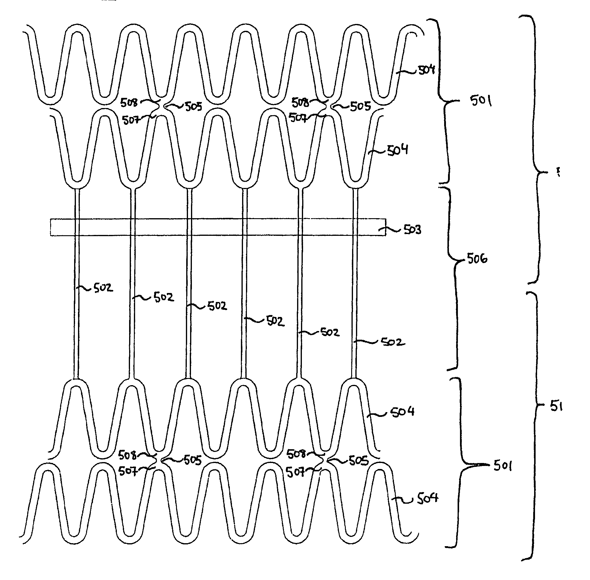
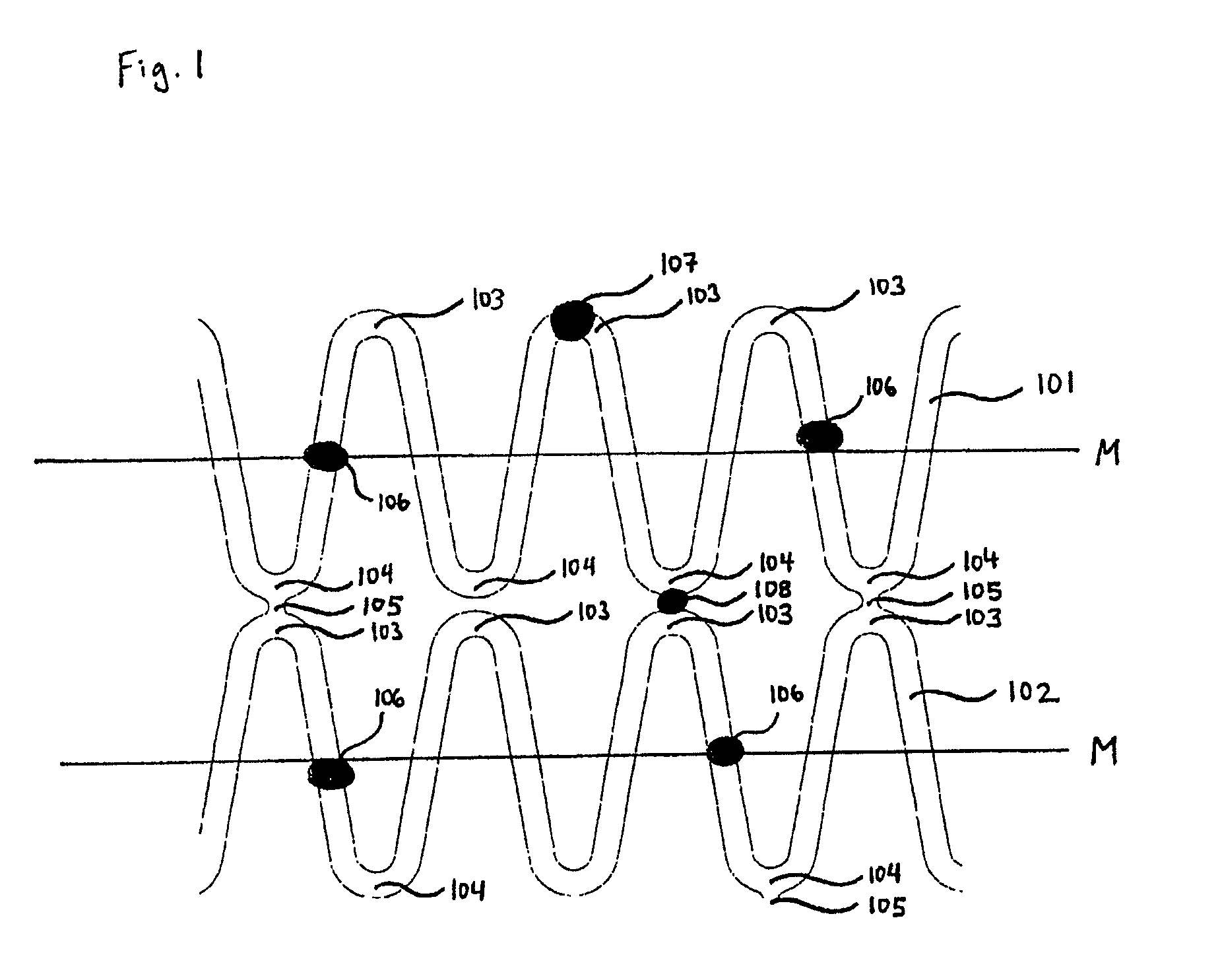
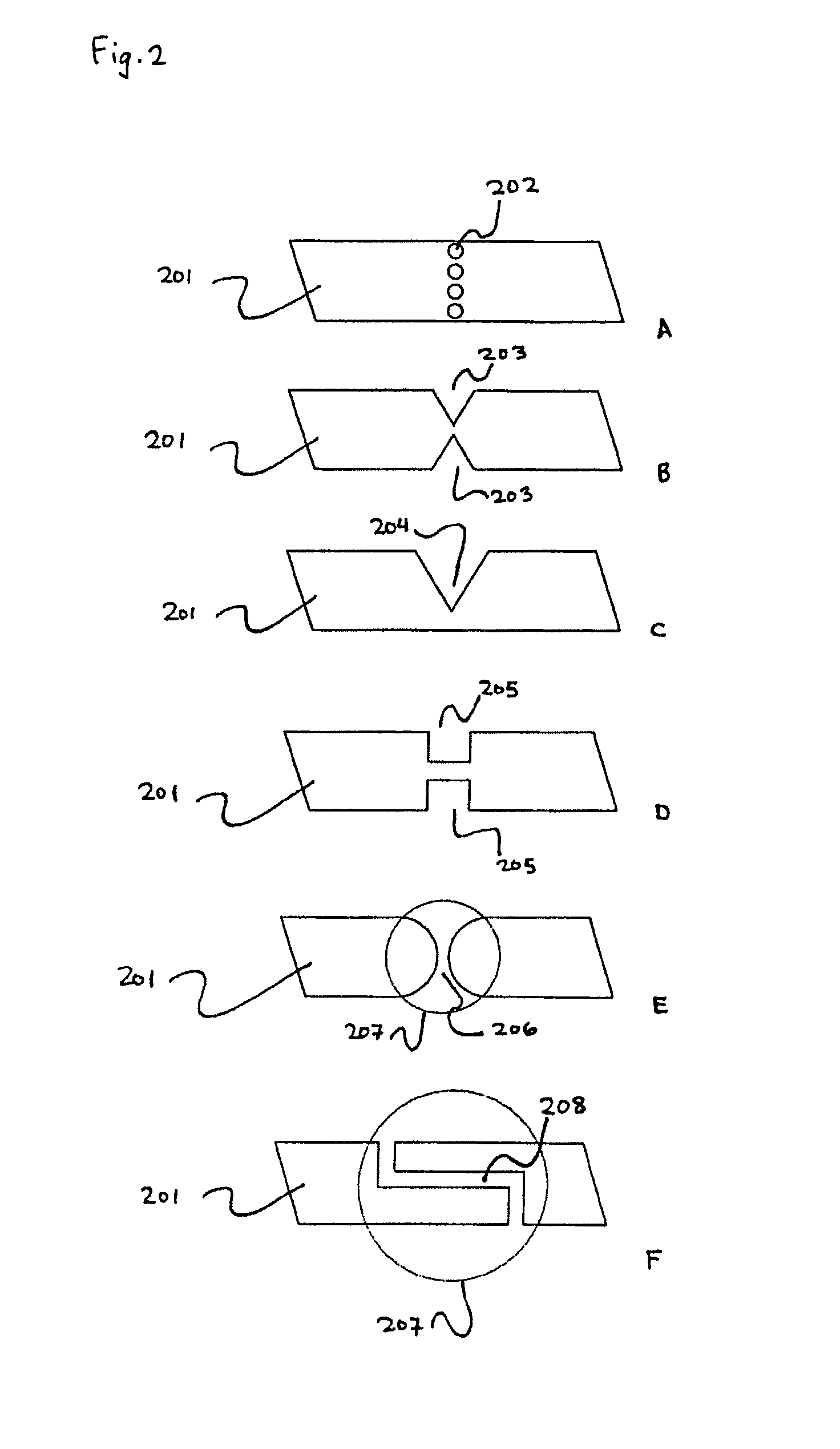
[0078]The supporting prosthesis is manufactured from highly precise material (e.g. 316L, L605, or nitinol) using a solid state laser. In order to freely design the supporting prosthesis, one strives for a method which allows user-defined cutting guidance on a tube. A laser fulfils these requirements in conjunction with a coordinate table, a round axis and a specially manufactured tube guider which precisely guides the tube in the required degrees of freedom under the laser cutting head. The supporting prosthesis structure and the predetermined breaking points, which are in this case mechanical (as for example depicted in FIG. 2) are cut into the tube in a one-step process. The middle part of the supporting prothes...


PUM


Abstract

The invention relates to a tubular supporting prosthesis, comprising two terminal regions relative to the longitudinal supporting prosthesis axis and a center region disposed between the two terminal regions, wherein every terminal region is provided with a mesh structure made of at least two structural rings, which are connected to each other via connecting members and are disposed point-symmetrically about the longitudinal supporting prosthesis axis. The center region is formed by elongated connecting members, which are connected to the structural rings respectively disposed adjacent to the center of the longitudinal supporting prosthesis axis. An aortic valve, which is produced by means of tissue engineering, is fastened and/or integrated in the center region.

Description

[0001]The invention relates to supporting prostheses with heart valves. In particular, the invention relates to supporting prostheses with heart valves, in particular for aortic valve replacement.BACKGROUND OF THE INVENTION[0002]As a rule, valve prostheses are introduced into the body as an integrated part of vessel supporting prostheses. Such supporting prostheses are as a rule tubular lattice structures which are also referred to as “stents”. Supporting prostheses with integrated valve replacement are known in the prior art. Such valves are obtained from cow, from pig as well as from horse. Supporting prostheses with tissue engineered (“TE”) valves are also known (Stock et al. (2006). J. Thorac. Cardiovasc. Surg. 131, 1323-30). As compared to a xenograft, tissue engineering in general offers the advantage that cells of any desired origin (e.g. homologous or autologous human cells) can be integrated into the structure of an existing decellularized, non-human valve (see EP 1499366)....

Claims


Application Information

Patent Timeline
IPC IPC(8): A61F2/06A61F2/24
CPCA61F2220/005A61F2250/0082A61F2/2418A61F2230/0054
Inventor HOERSTRUP, SIMON-PHILIPPZUND, GREGORFLIEDNER, THILOBAAIJENS, FRANK
Owner UNIV ZURICH
Why Eureka
Try Eureka