Optical transmitter, optical transmission method, and wavelength-selective variable delayer

a wavelength-selective variable delayer and optical transmission technology, applied in the field of optical transmission methods, can solve the problems of affecting the reception quality of phase modulation optical signals, severe waveform degradation, and degrade transmission performance, so as to reduce transmission quality degradation, enhance system performance, and improve network flexibility. the effect of design and management flexibility

Inactive Publication Date: 2014-01-07
FUJITSU LTD
View PDF16 Cites 6 Cited by
  • Summary
  • Abstract
  • Description
  • Claims
  • Application Information

AI Technical Summary

Benefits of technology

[0034]The present invention has been made in view of the circumstances described above. Accordingly, an object of the present invention is to suppress transmission quality degradation in network systems where intensity modulation and phase modulation optical signals are multiplexed.
[0058]Thus, the present invention is capable of suppressing transmission quality degradation in network systems where intensity modulation and phase modulation optical signals are multiplexed together. In addition, because transmission systems can be upgraded by phase modulation optical signals, the enhancement of system performance (a wavelength utilization factor, an OSNR (optical signal-to-noise ratio) characteristic, etc.) can be expected, and the flexibility of network design and management can be increased.

Problems solved by technology

Because of this, as shown in FIGS. 43C and 43D, the residual chirp ΔC during each relay span is multiplied by the number of relay stages, resulting in severe waveform degradation.
In the case of intensity modulation optical signals, the residual chirp causes jitter (deviation from the center position of a received pulse) at the signal receiving end, and in the case of phase modulation optical signals, the residual chirp becomes the direct noise component of a symbol code and degrades transmission performance.
However, in upgrading transmission systems, when it is necessary to multiplex and transmit intensity modulation and phase modulation optical signals, nonlinear effects (cross-phase modulation) due to variations in the intensity of an intensity modulation optical signal greatly affect the reception quality of phase modulation optical signals.
However, in transmission systems with transmission fibers whose chromatic dispersion is small per unit of length, if the function of multiplexing phase modulation optical signals such as DQPSK signals is added, in nonzero dispersion-shifted fibers it cannot prove definitely that the code walk-off (or relative propagation speed difference in a transmission fiber) between wavelength channels is great enough to avoid the influence of cross-phase modulation that phase modulation optical signals undergo.

Method used


Image

  • Optical transmitter, optical transmission method, and wavelength-selective variable delayer
  • Optical transmitter, optical transmission method, and wavelength-selective variable delayer
  • Optical transmitter, optical transmission method, and wavelength-selective variable delayer

Examples


first embodiment

[A] First Embodiment

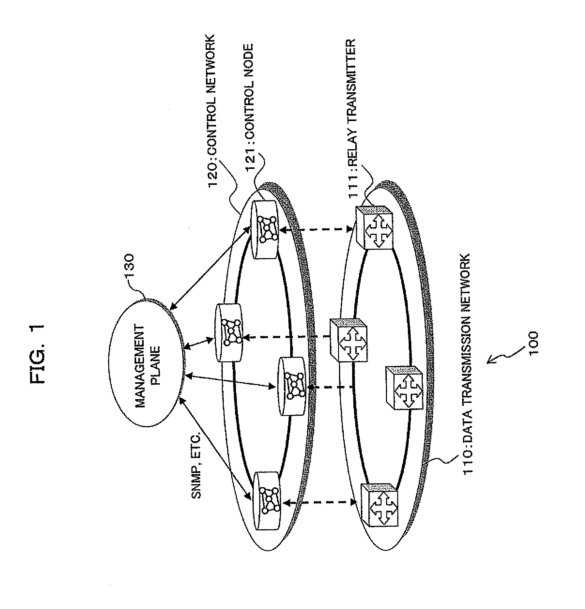
[0091]Referring to FIG. 1, there is shown a network system to which an optical transmitter according to a first embodiment of the present invention is applied. The network system 100 shown in the figure is constituted by a data transmission network 110, a control network 120 which controls the data transmission network 110, and a management plane 130 which manages the control network 120. The data transmission network 110 includes a plurality of optical transmitters 111, which are interconnected. The control network 120 includes a plurality of control nodes 121, which are connected with one another and disposed so as to correspond to the optical transmitters 111 forming the data transmission network 110.

[0092]With the above configuration, the control nodes 121 forming the control network 120 extract information from the optical transmitters (relay transmitters) 111 of the data transmission network 110 (which are target objects in the data transmission network 110...

second embodiment

[B] Second Embodiment

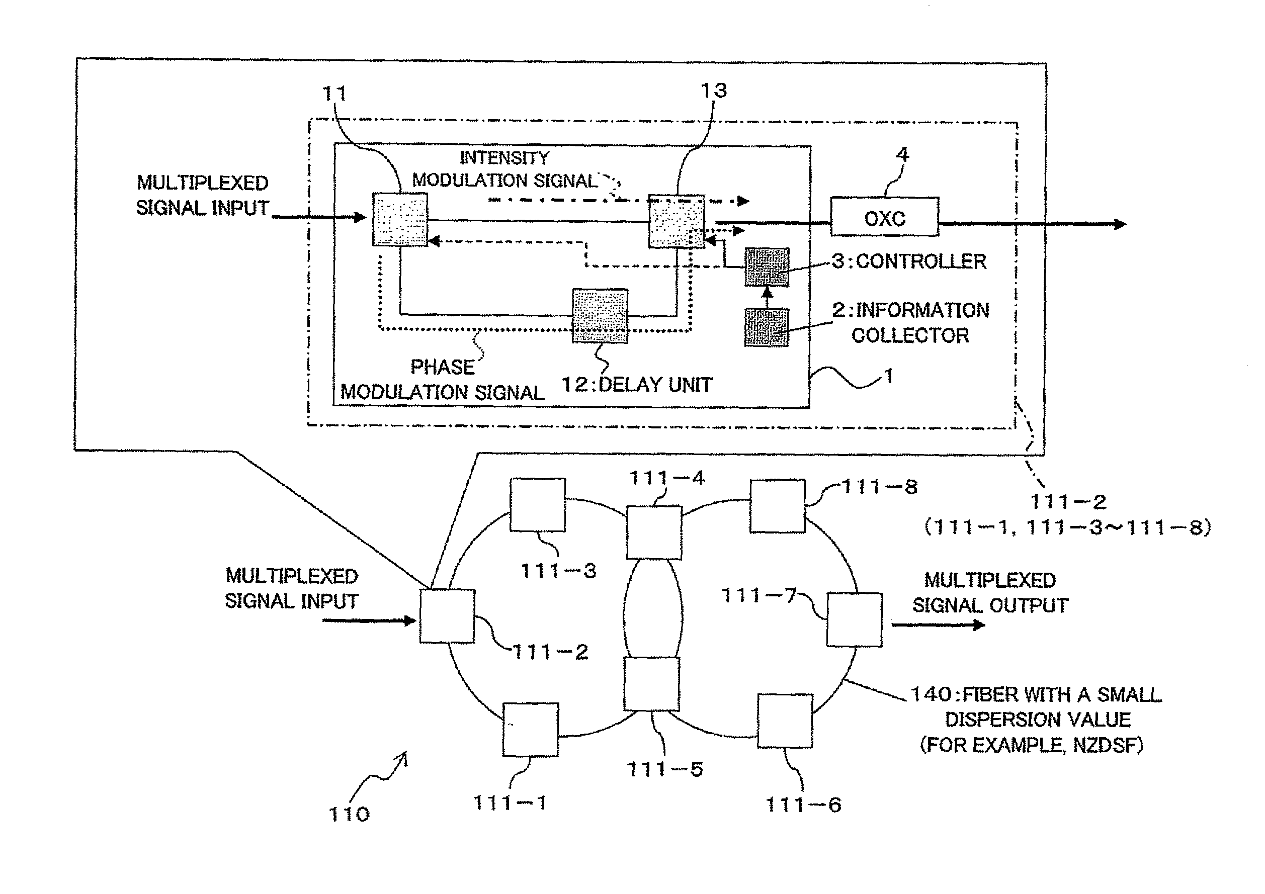
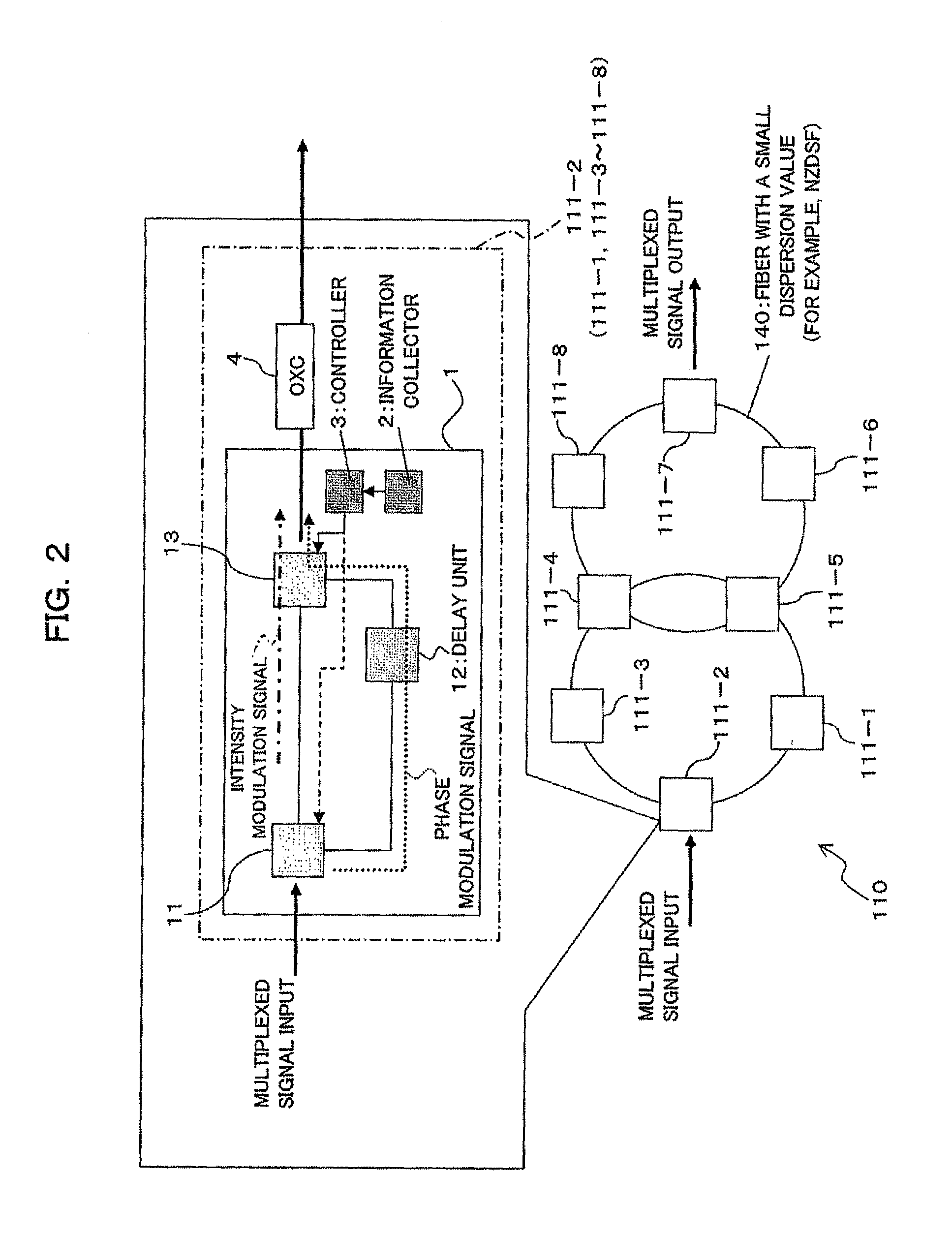
[0162]Referring to FIG. 20, there is shown an optical transmitter 111A according to a second embodiment of the present invention. The optical transmitter 111A differs from the optical transmitter 111 (see FIG. 2) of the first embodiment in that a delay block 1A includes a chromatic dispersion giving unit (bit time difference giving unit) 12A instead of the delay unit 12. The remaining parts other than this are basically the same as the first embodiment. In FIG. 20, the same reference numerals as FIG. 2 denote approximately the same parts.

[0163]That is, in an optical coupler 11 as the splitting unit 11, the input signal (multiplexed signal) is split into two signals. One of the two signals, as it is, is output to a wavelength-selective switch 13 serving as the combining unit 13. The other signal is further given chromatic dispersion in the chromatic dispersion giving unit 12A. This gives a difference in chromatic dispersion between the one optical signal, which i...

third embodiment

(C) Third Embodiment

[0173]Referring to FIG. 25, there is shown an optical transmitter according to a third embodiment of the present invention. The optical transmitter shown in the figure is adapted to transmit a wavelength multiplexed signal of an intensity modulation optical signal and a phase modulation optical signal through a transmission line. This optical transmitter includes an intensity modulation signal generator 41 which outputs at least one intensity modulation optical signal over at least one channel (in this embodiment, a plurality of channels), and a phase modulation signal generator 42 which outputs at least one phase modulation optical signal over at least one channel (in this embodiment, a plurality of channels). The optical transmitter further includes a chromatic dispersion loader 43, combiners 44a to 44c, an information collector 2, and a controller 3B.

[0174]The first input combiner 44a is used for combining (wavelength-multiplexing) the intensity modulation opt...


PUM


Abstract

An optical transmitter is provided for transmitting a wavelength multiplexed signal comprising an intensity modulation optical signal and a phase modulation optical signal through a transmission line. The optical transmitter includes a bit time difference given signal generator for generating at least two optical signals having a bit time difference therebetween, from the wavelength multiplexed signal. The optical transmitter further includes a wavelength multiplexed signal output unit to which at least two optical signals are input from the bit time difference given signal generator, and which generates and outputs a wavelength multiplexed signal in which the bit time difference was given between the phase modulation optical signal and the phase modulation optical signal.

Description

BACKGROUND OF THE INVENTION[0001]1) Field of the Invention[0002]The present invention relates to optical transmitters and optical transmission methods suitable for use in optical WDM (Wavelength-Division Multiplexing) communication systems.[0003]2) Description of the Related Art[0004]WDM transmission techniques, which employ 2.5-Gbps (Gbit / s) or 10-Gbps intensity modulation (on-off keying) optical signals of tens of wavelengths, have now been put to practical use in land transmission systems and submarine transmission systems, such as access network systems, metro network systems, long-distance network systems, etc. For 40-Gbps WDM systems that will be put to practical use in a short time, element techniques and development of devices have accelerated in recent years, and the 40-Gbps WDM systems are required to have the same transmission distance and frequency utilization factor as the 10-Gbps transmission systems.[0005]As a means of realizing 40-Gbps WDM transmission systems, deep ...

Claims


Application Information

Patent Timeline
Patent Type & Authority Patents(United States)
IPC IPC(8): H04B10/00H04B10/275H04J14/00H04B10/556H04B10/54H04B10/29H04B10/032H04B10/524H04B10/299H04B10/2507H04J14/02H04B10/077H04B10/516H04B10/58H04B10/25H04B10/61
CPCH04J14/0204H04J14/025H04J14/0283H04J14/0286H04J14/0246H04J14/022H04J14/0212H04J14/0217H04J14/0221H04B10/2557H04J14/0227H04J14/0219H04B10/516
Inventor TANAKA, TOSHIKINAKASHIMA, HISAOHOSHIDA, TAKESHIKATAGIRI, TORUOOI, HIROKIMIURA, AKIRA
Owner FUJITSU LTD
Why Eureka
Try Eureka