Hydrogen production device and method for producing hydrogen
a technology of hydrogen production device and hydrogen production method, which is applied in the direction of oxygen/ozone/oxide/hydroxide, manufacturing tools, instruments, etc., can solve the problems of difficult to complement a long-term fluctuation, low operation rate of electric power facilities, and high cost of electricity and heat production, so as to achieve high light use efficiency and high light use efficiency. , the effect of high light use efficiency
- Summary
- Abstract
- Description
- Claims
- Application Information
AI Technical Summary
Benefits of technology
Problems solved by technology
Method used
Image

Examples
example 1
1. Example 1
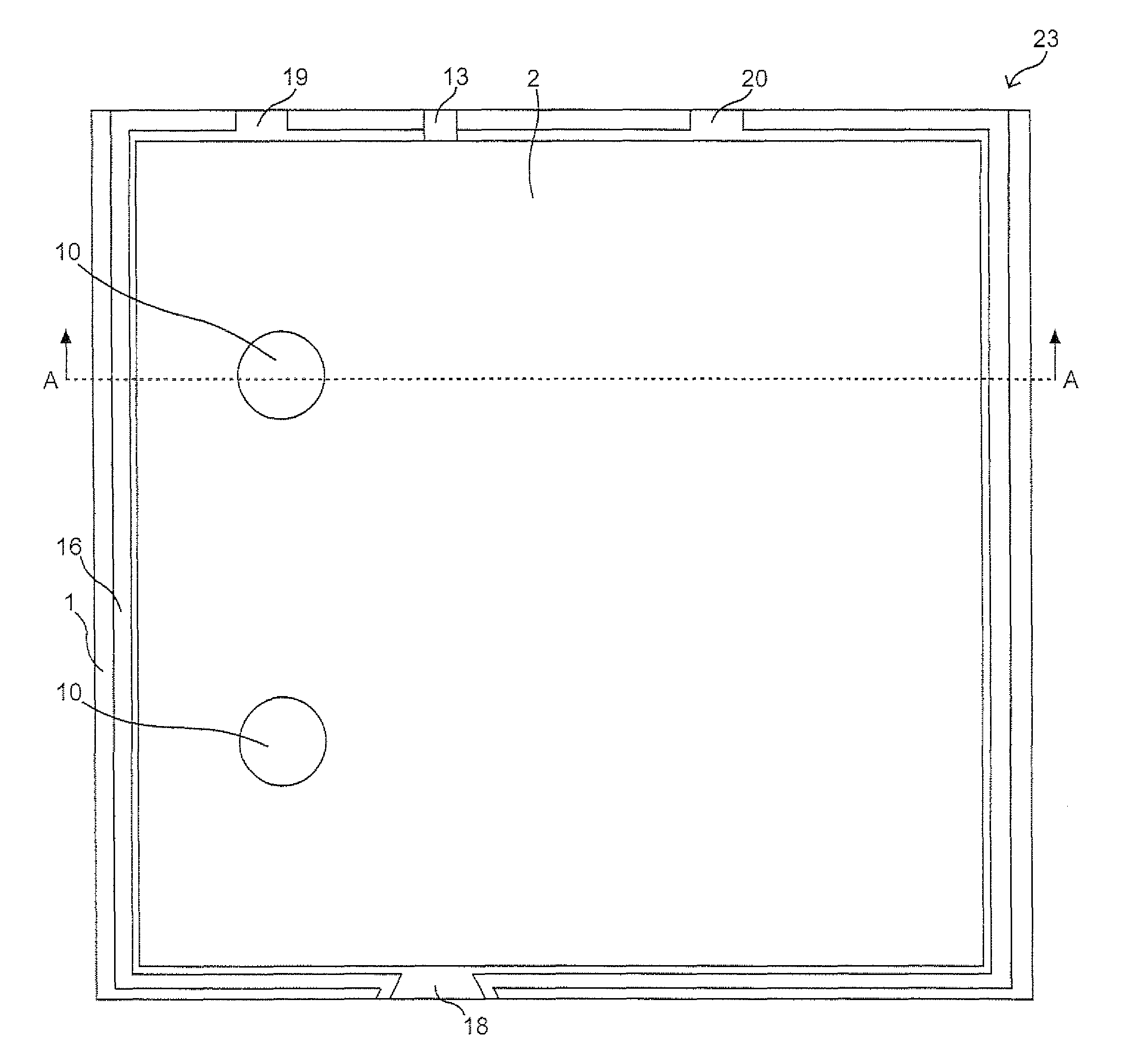
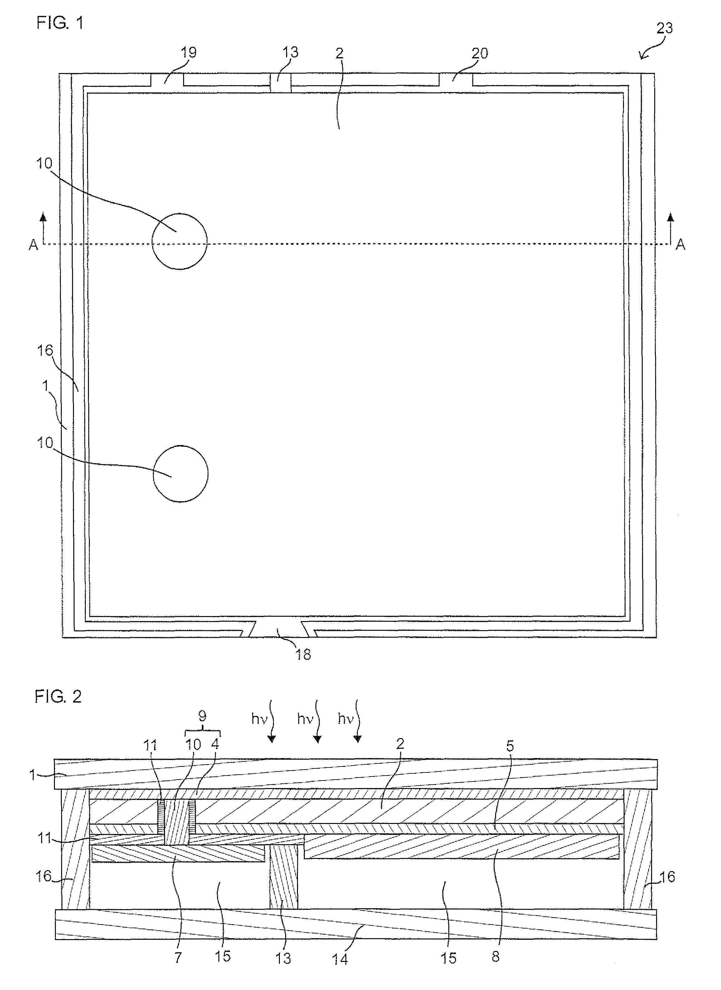
[0191]The following hydrogen production device as shown in FIGS. 1 to 3 was produced.
[0192]In the produced hydrogen production device, an SnO2 thin film serving as the first electrode 4 is formed on a glass substrate serving as the substrate 1. The two-junction photoelectric conversion part 3 formed of an a-SiGe layer and an a-Si layer is laminated on the first electrode 4, and the second electrode 5 formed of a transparent electrode layer made of indium tin oxide (ITO) is provided thereon. The hydrogen generation part (first gas generation part 8) supporting the hydrogen generation catalyst is provided on the second electrode 5, while the oxygen generation part (second gas generation part 7) supporting the oxygen generation catalyst is provided so as to be isolated from the second electrode 5 with the insulation part 11 formed of a polyimide film and connected to the first electrode 4 through the second conductive part 10 made of an Ag paste. The electrolytic solution p...
example 2
2. Example 2
[0198]The hydrogen production device as shown in FIG. 4 was produced on the following condition.
[0199]The photoelectric conversion part 2, the second electrode 5, the insulation part 11, the second conductive part 10, the oxygen generation part (second gas generation part 7), and the hydrogen generation part (first gas generation part 8) were formed on the substrate 1 by the same method as in the example 1. Here, this example is different from the example 1 in that the contact hole having the second conductive part 10 is provided along a longitudinal axis direction of the second gas generation part 7. In this case, since the number of the contact holes is reduced, a contact defect can be prevented, and a contact can be formed such that a cross-section area of the contact hole is narrower than a width of the second gas generation part 7 connected to the second conductive part 10 even when the width of the second gas generation part 7 is narrowed, so that hydrogen and oxyg...
example 3
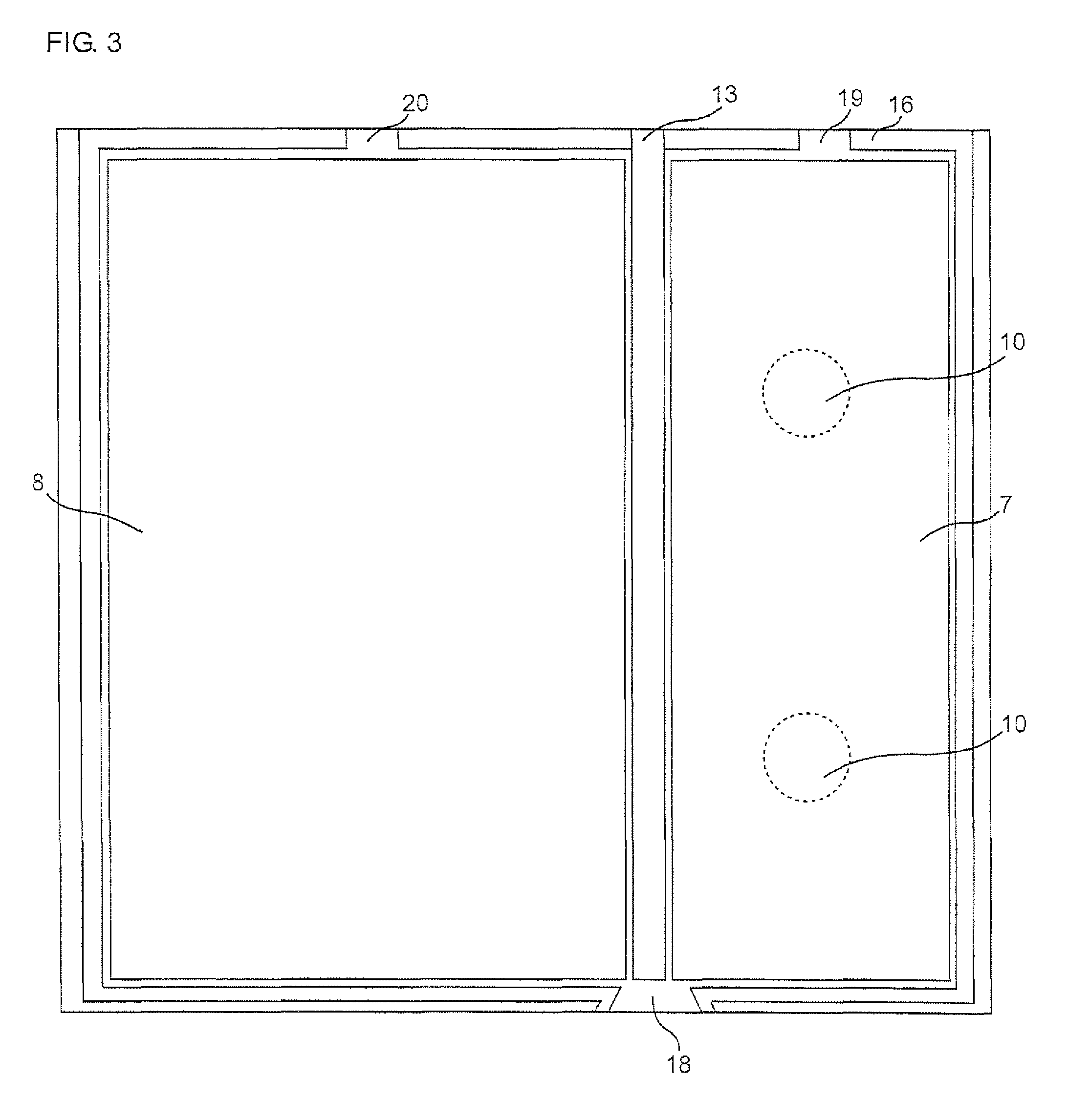
3. Example 3
[0200]The hydrogen production device as shown in FIG. 5 was produced on the following condition.
[0201]The photoelectric conversion part 2, the second electrode 5, the insulation part 11, the second conductive part 10, the oxygen generation part (second gas generation part 7), and the hydrogen generation part (first gas generation part 8) were formed on the substrate 1 by the same method as in the example 1.
[0202]Then, as shown in FIG. 5, the partition wall 13 was formed by applying thermal curing polyimide to a position between the first gas generation part 8 and the second gas generation part 7 by a screen printing method so that the gas can be efficiently collected, and then the device was sealed by connecting the material on the substrate and the plate with the seal material. Thus, the hydrogen production device was produced.
PUM
| Property | Measurement | Unit |
|---|---|---|
| sunlight transmittance | aaaaa | aaaaa |
| sunlight transmittance | aaaaa | aaaaa |
| sunlight transmittance | aaaaa | aaaaa |
Abstract
Description
Claims
Application Information
 - R&D
- Intellectual Property
- Life Sciences
- Materials
- Tech Scout
- Unparalleled Data Quality
- Higher Quality Content
- 60% Fewer Hallucinations
Browse by: Latest US Patents, China's latest patents, Technical Efficacy Thesaurus, Application Domain, Technology Topic, Popular Technical Reports.
© 2025 PatSnap. All rights reserved.Legal|Privacy policy|Modern Slavery Act Transparency Statement|Sitemap|About US| Contact US: help@patsnap.com