

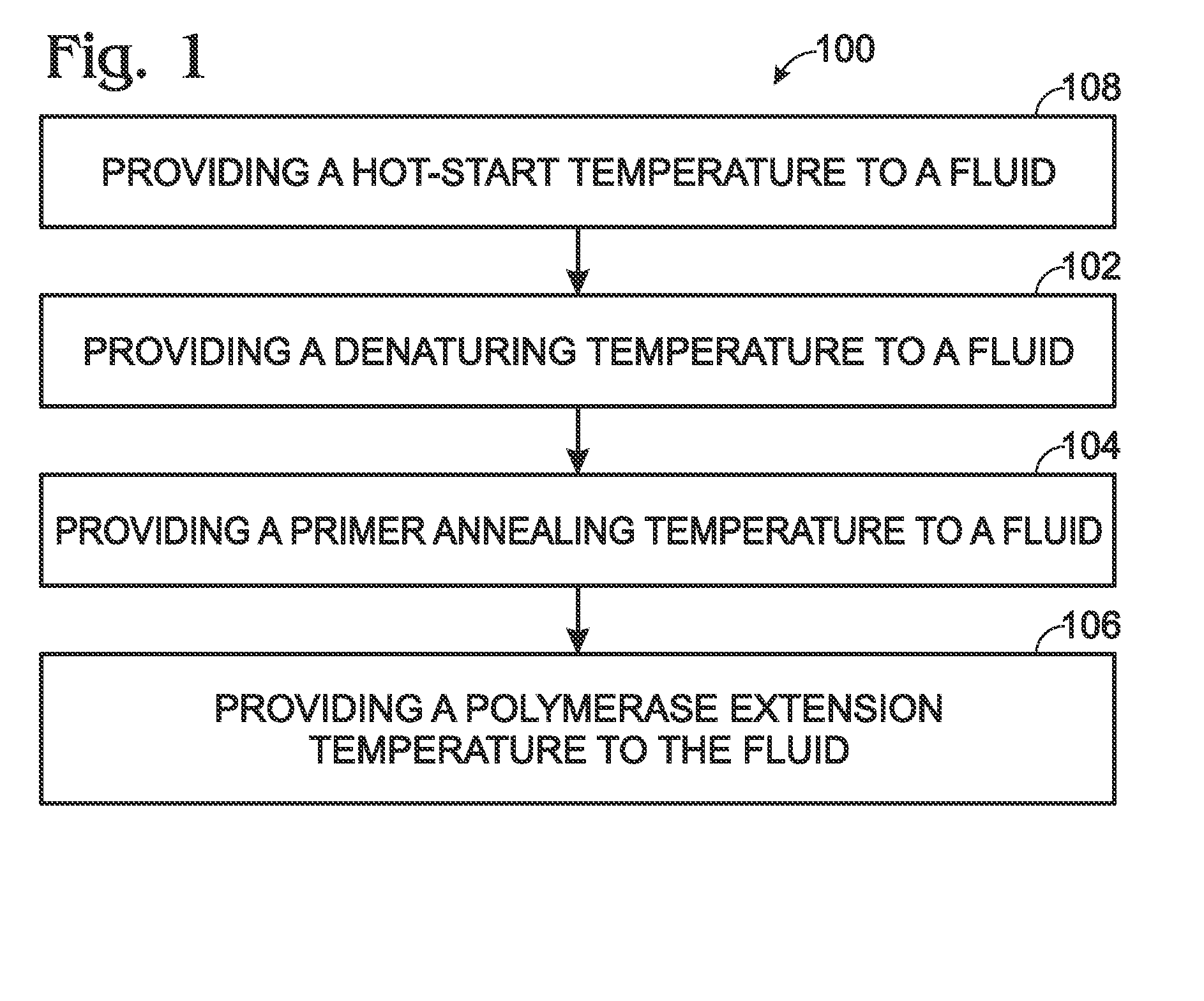
Flow-based thermocycling system with thermoelectric cooler
a thermoelectric cooler and thermocycling technology, which is applied in the field of flow-based thermocycling systems with thermoelectric coolers, can solve the problems of not optimizing the activity of primers and/or polymerases, limiting the accuracy of this measurement, and fundamentally limited reaction times of current rtpcr instruments
- Summary
- Abstract
- Description
- Claims
- Application Information
AI Technical Summary
Benefits of technology
Problems solved by technology
Method used
Image

Examples
example 1
Exemplary Flow-Based Thermocycler with Hot-Start Region
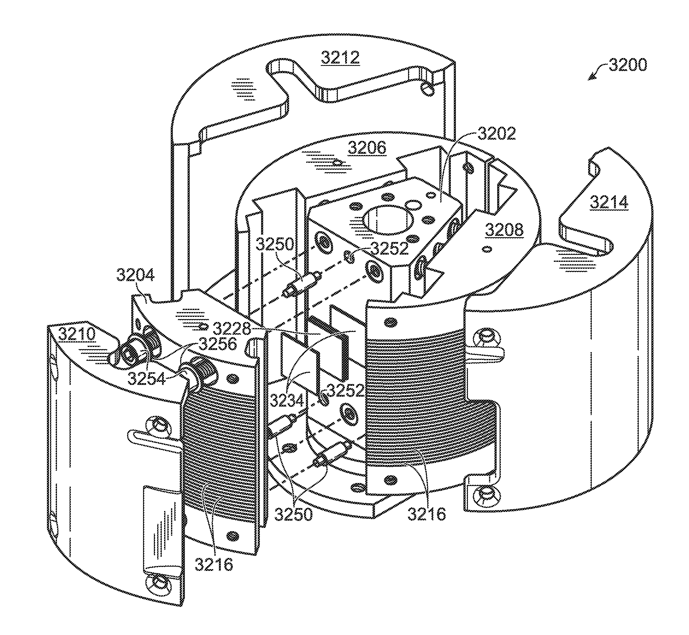
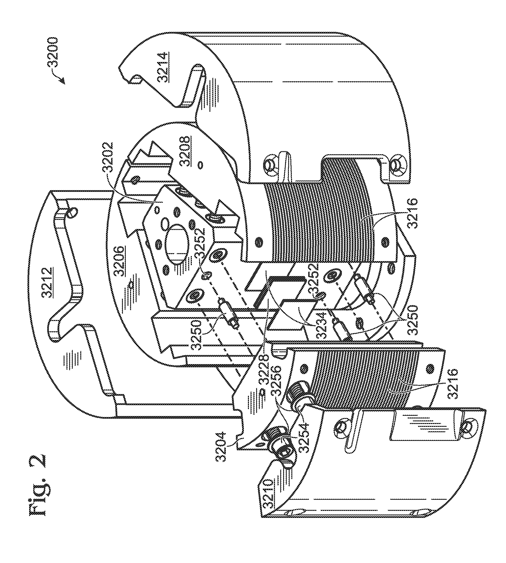
[0075]This example describes an exemplary thermocycler 3200 containing a hot-start region, in accordance with aspects of the present disclosure; see FIG. 10.
[0076]Various modifications and / or additions may be made to the exemplary embodiments of FIGS. 2-9 according to the present disclosure. For example, a “hot start” mechanism may be added to facilitate a high-temperature PCR activation step. FIG. 10 shows a central portion (i.e., outer segments not shown) of an exemplary thermocycler 3200 including a hot start region 3258, which is separated from the remainder of the thermocycler by a gap 3259. The hot start region, like the inner segments, is configured to accept fluidic tubing, but is separated from the inner segments by gap 3259 to avoid unwanted heat conduction between the hot start region and the other portions of the thermocycler. A separate core portion (not shown) may be configured to heat region 3258 to a relatively h...
example 2
Exemplary Heating Configurations for Thermocyclers
[0078]This example describes various exemplary heating configurations for exemplary thermocyclers 3202a-h in accordance with aspects of the present disclosure; see FIGS. 11-18.
[0079]FIGS. 11-18 are schematic diagrams depicting top views of the thermocyclers. These diagrams, like FIG. 7, correspond to and are topologically equivalent to three-dimensional cylindrical thermocycling units. The thermocyclers each include three inner (e.g., melt, anneal, and extend) segments 3204a-h, 3206a-h 3208a-h in thermal contact with fluidic tubing 3218a-h for carrying samples undergoing PCR. The segments, in turn, each may (or optionally may not) be in thermal contact with respective (e.g., melt, anneal, and extend) heating elements 3254a-h, 3256a-h, 3258a-h (denoted by vertical bars) for delivering heat to the segments. The segments also may be in direct or indirect contact with one or more TECs (indicated by cross-hatching), one or more thermal co...
example 3
Exemplary Thermocycler Instrument
[0088]This example describes a thermocycler disposed within an exemplary instrument that also includes other components such as a cooling mechanism and a protective housing; see FIG. 19.
[0089]FIG. 19 generally depicts an exemplary thermocycling instrument 3400 at various stages of assembly. Instrument 3400 includes a thermocycler, generally indicated at 3402, which is substantially similar to thermocycler 3200 described above, but which generally may take various forms, including one or more features of any of the thermocyclers described in the previous examples. The instrument may include additional components, such as a front plate, a connection port, a heat sink, a cooling fan, and / or a housing, as described below.
[0090]A front plate 3404 is attached to the thermocycler with a plurality of fasteners 3406 that pass through central apertures 3408 in the front plate and complementary apertures in the thermocycler. The front plate helps to isolate the...
PUM
| Property | Measurement | Unit |
|---|---|---|
| temperature | aaaaa | aaaaa |
| temperature | aaaaa | aaaaa |
| temperature | aaaaa | aaaaa |
Abstract
Description
Claims
Application Information