Data communication apparatus, data communication system, and data communication method

a data communication apparatus and data communication technology, applied in the field of data communication, can solve the problems of increasing the cost of a total system, increasing the cost of a chip area, and the component included in the data carrier device becomes larger, so as to reduce the size of the system, reduce the voltage amplitude inputting to the data communication apparatus, and reduce the cost

Inactive Publication Date: 2014-01-28
CANON KK
View PDF7 Cites 0 Cited by
  • Summary
  • Abstract
  • Description
  • Claims
  • Application Information

AI Technical Summary

Benefits of technology

[0009]An object of the present invention is to provide a data communication technology which can reduce the size of a system by enabling bidirectional data communication in two contact points, and enables a cheap system configuration in the system in which two data communication apparatuses communicate data.
[0015]The size of a system can be reduced, because the system can communicate data as connecting with two terminals. A voltage amplitude inputting to the data communication apparatus can be reduced, so that the cost can be reduced by lowering the withstand voltage of a component. In addition, since it is not necessary to accurately maintain a cycle for transmitting and receiving data to be constant, the cost of the data communication system can be reduced.

Problems solved by technology

However, the above bidirectional data communication system includes the following problem.
Thus, the following is a problem: a component included in the data carrier device becomes larger, and the cost is increased due to the increase of a chip area.
In this method, it is necessary to severely control the duty ratio of the input pulse signal, and to cause the data carrier driving device to be an expensive system configured with a microcomputer, and the like, so that this is also a problem to increase a cost of a total system.

Method used


Image

  • Data communication apparatus, data communication system, and data communication method
  • Data communication apparatus, data communication system, and data communication method
  • Data communication apparatus, data communication system, and data communication method

Examples


Embodiment Construction

[0023]Next, exemplary embodiments for implementing the present invention will be described in detail as referring to the drawings.

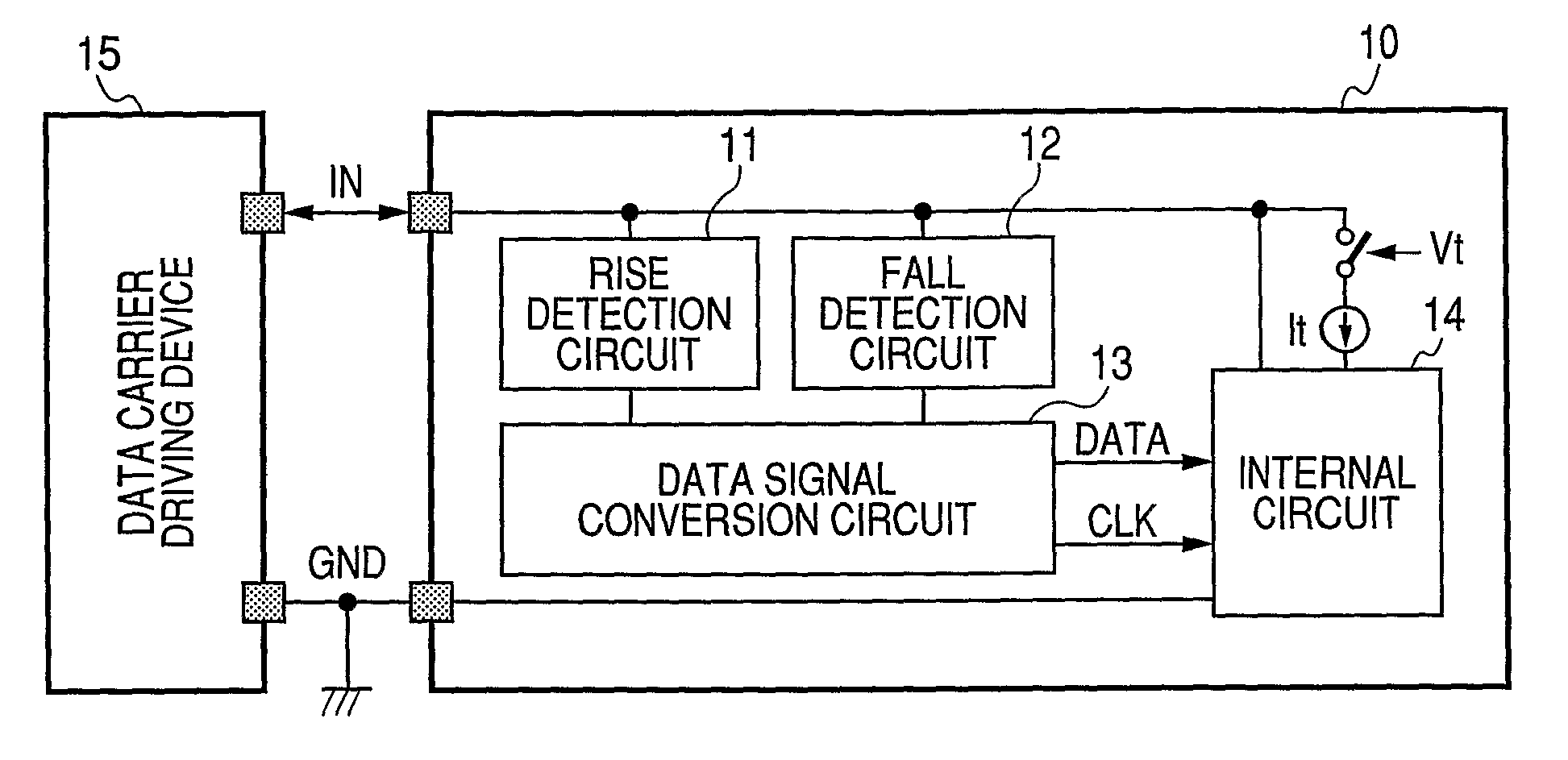
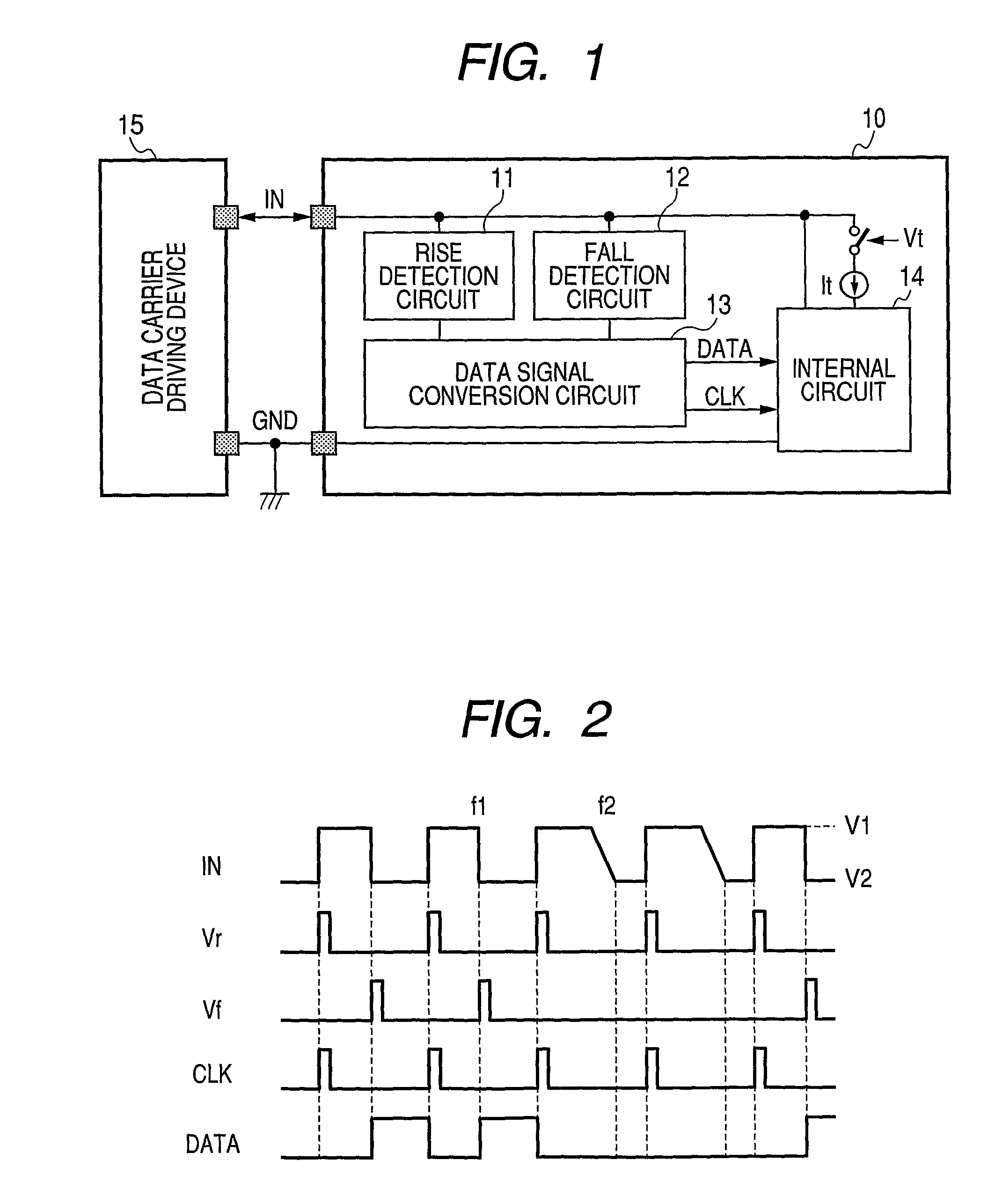
[0024]FIG. 1 is a block diagram illustrating a data communication system including a data carrier device 10 and a data carrier driving device 15 thereof according to an exemplary embodiment of the present invention. In FIG. 1, Reference numeral 10 denotes a data carrier device (a second data communication apparatus) for communicating data at two contact points with the data carrier driving device 15, and includes two terminals of a terminal IN (signal terminal) and a terminal GND (reference voltage terminal). Reference numeral 15 denotes a data carrier driving device (a first data communication apparatus) as a control device. The data carrier driving device 15 and the data carrier device 10 are connected only at two contact points of the terminal IN and the terminal GND to communicate data through such two contact points. The data carrier device 10 genera...


PUM


Abstract

An object of the present invention is to provide a data communication technique which can reduce a size of a system by enabling bidirectional data communication, and enables a cheap system configuration. A data communication apparatus is provided, the data communication apparatus including a signal terminal (IN) for inputting receiving signals of pulses of which rise times or fall times are mutually different, a reference voltage terminal (GND) for inputting a reference voltage, a rise detection circuit (11) for detecting a rise or a rise time of the receiving signal, a fall detection circuit (12) for detecting a fall or a fall time of the receiving signal, a data signal conversion circuit (13) for generating a clock signal or a data signal based on a result of a detection by the rise detection circuit or the fall detection circuit, and an internal circuit (14) for inputting the clock signal or the data signal generated by the data signal conversion circuit, and for outputting a transmission signal to the signal terminal.

Description

TECHNICAL FIELD[0001]The present invention relates to data communication, particularly, to data communication between data communication apparatuses.BACKGROUND ART[0002]Japanese Patent Application Laid-Open No. 2006-135888 describes, for example, such a configuration that bidirectional data communication is enabled between two contact points to reduce the size of a system in which a data carrier device and a data carrier driving device execute bidirectional data communication.[0003]In a data communication system described in the above Japanese Patent Application Laid-Open No. 2006-135888, the data carrier device includes a signal terminal for inputting a signal from the data carrier driving device and a reference voltage terminal for inputting a reference voltage. The signal input from the data carrier driving device to the signal terminal of the data carrier device includes a part whose duty ratio is different, and is a pulse signal whose pulse frequency is constant as a whole. The...

Claims


Application Information

Patent Timeline
Patent Type & Authority Patents(United States)
IPC IPC(8): H04L7/02
CPCH03K5/1534H04L25/493H04L25/028H04L25/0264H04L5/14H04L25/02
Inventor YAMAZAKI, YOSHIKAZU
Owner CANON KK
Why Eureka
Try Eureka