
Method for membrane backwashing and backwashing apparatus

a backwashing apparatus and membrane technology, applied in the direction of moving filter element filters, separation processes, filtration separation, etc., can solve the problems of reducing the efficiency of the filtration apparatus, detracting from the degree of flexibility, etc., to reduce the effectiveness of the backwashing effect, reduce the volume of backwashing waste water, and enhance the flexibility of equipment arrangement

Active Publication Date: 2014-02-04
METAWATER CO LTD
View PDF22 Cites 3 Cited by
  • Summary
  • Abstract
  • Description
  • Claims
  • Application Information

AI Technical Summary

Benefits of technology

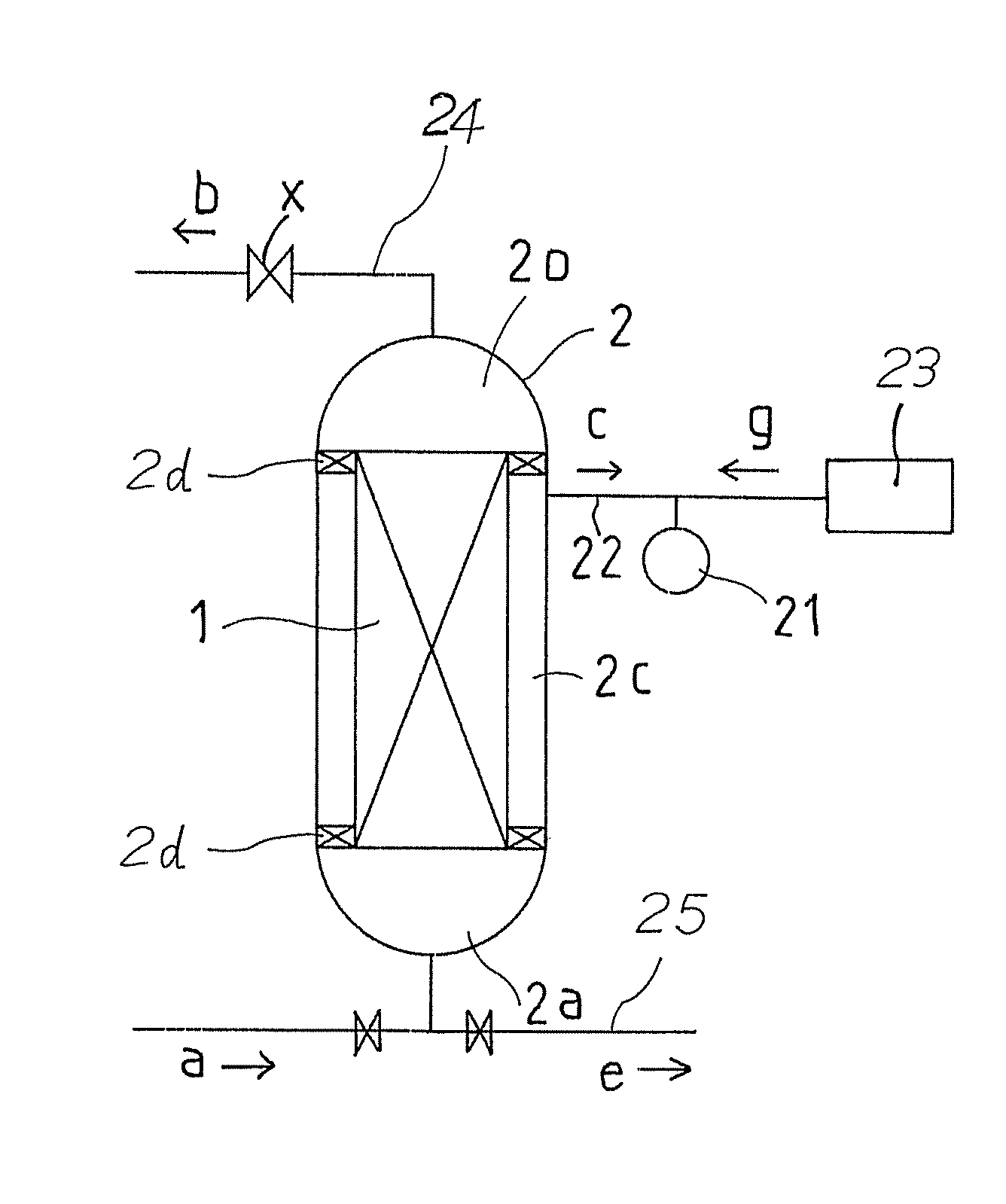
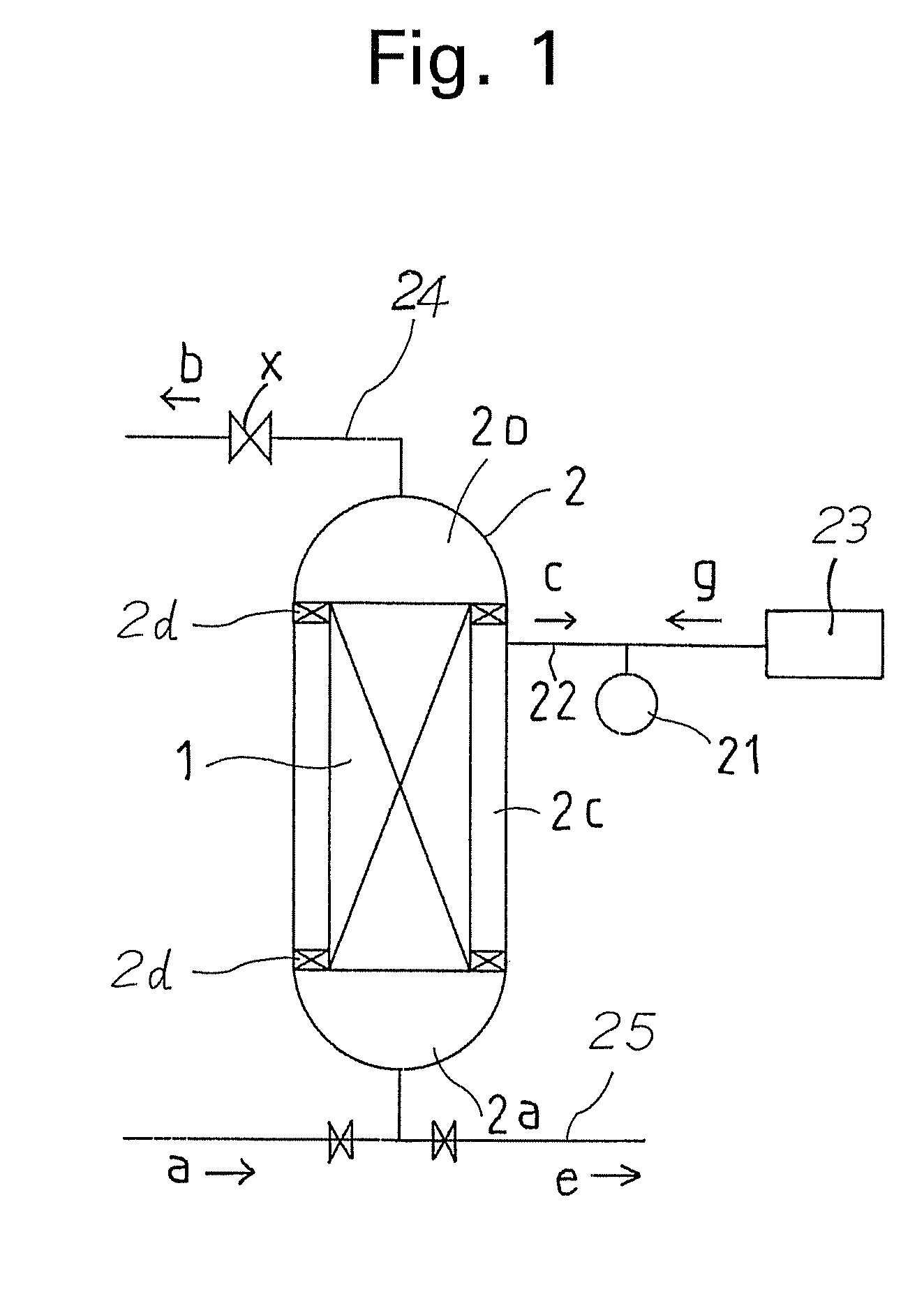
The present invention provides a filtration membrane clogged with fouling substances, which is cleared using air pressure to replace water in the membrane. The drained water is gradually reduced, and air pressure is increased to push out the remaining water and peel off the fouling substances. This results in a smaller volume of wastewater, which can be drained without the need for larger pipes. The invention also includes a filtration water header pipe that serves as an air feed pipe, allowing for backwashing while preventing water from flowing back. This leads to improved water recovery and reduced wastewalls.

Problems solved by technology

As a result, a problem arises insofar that the operational efficiency of the filtration apparatus diminishes.
However, in both of these cases, one where the filtrated water is used, and the other where high-pressurized air is used to effect the backwashing operation, a large amount of water that has been lodged in the membrane element 1 is suddenly pushed toward the primary side at one and the same time.
However, this in itself is an impediment to membrane filtration equipment compact and also making the detracts from the degree of flexibility that is desirable in the arrangement of the equipment.

Method used


Image

  • Method for membrane backwashing and backwashing apparatus
  • Method for membrane backwashing and backwashing apparatus
  • Method for membrane backwashing and backwashing apparatus

Examples


example

[0062]Hereinafter, an embodiment of the present invention will be described.

[0063]In a case where a membrane element 1 having a diameter of 180 mm and a length of 1000 mm, and containing therein 2000 channels of filtration channels (cells) each having an inner diameter of 2.5 mm, is accommodated in a casing 2 having a diameter of 200 mm, if one defines the volume of the casing (excluding the inlet chamber and the outlet chamber) as 100%, the volume of a secondary chamber 2c is 21%, the volume of a filtration element 1 is 48%, and the volume of a filtration channel is 31%. Further, in the membrane element 1, when the water ratio for a substrate layer and a separating layer is set at 9:1, and the porous rate of the substrate layer and the separating layer is set at 50%, the amounts of filtrated water remaining in the substrate layer and the separating layer are respectively 21% and 2.5%.

[0064]In a conventional backwashing method, the water in the secondary chamber of the casing amount...


PUM

PropertyMeasurementUnit
diameteraaaaaaaaaa
diameteraaaaaaaaaa
lengthaaaaaaaaaa

Abstract

A backwashing method incorporating a membrane filtration apparatus in which a ceramic filtration membrane including a substrate layer 11b having an extremely large number of filtration pores and a separating layer 11a having filtration pores smaller than those of the substrate layer is accommodated in a casing. Air controlled to a pressure p1 is supplied to the secondary side of the filtration membrane so as to drain the filtrated water in the membrane filtration apparatus gradually toward the primary side. After that, air pressure is increased to p3 so as to push the water in the filtration membrane toward the primary side together with the air, thereby peeling off any fouling substances. Unlike in conventional cases, a large amount of backwashing drain water is at no time drained at any one time, and thus, without reducing the effectiveness of backwashing, a backwashing drain pipe can be designed to have a small diameter. As a result, equipment can be reduced in size and the flexibility of equipment can be enhanced.

Description

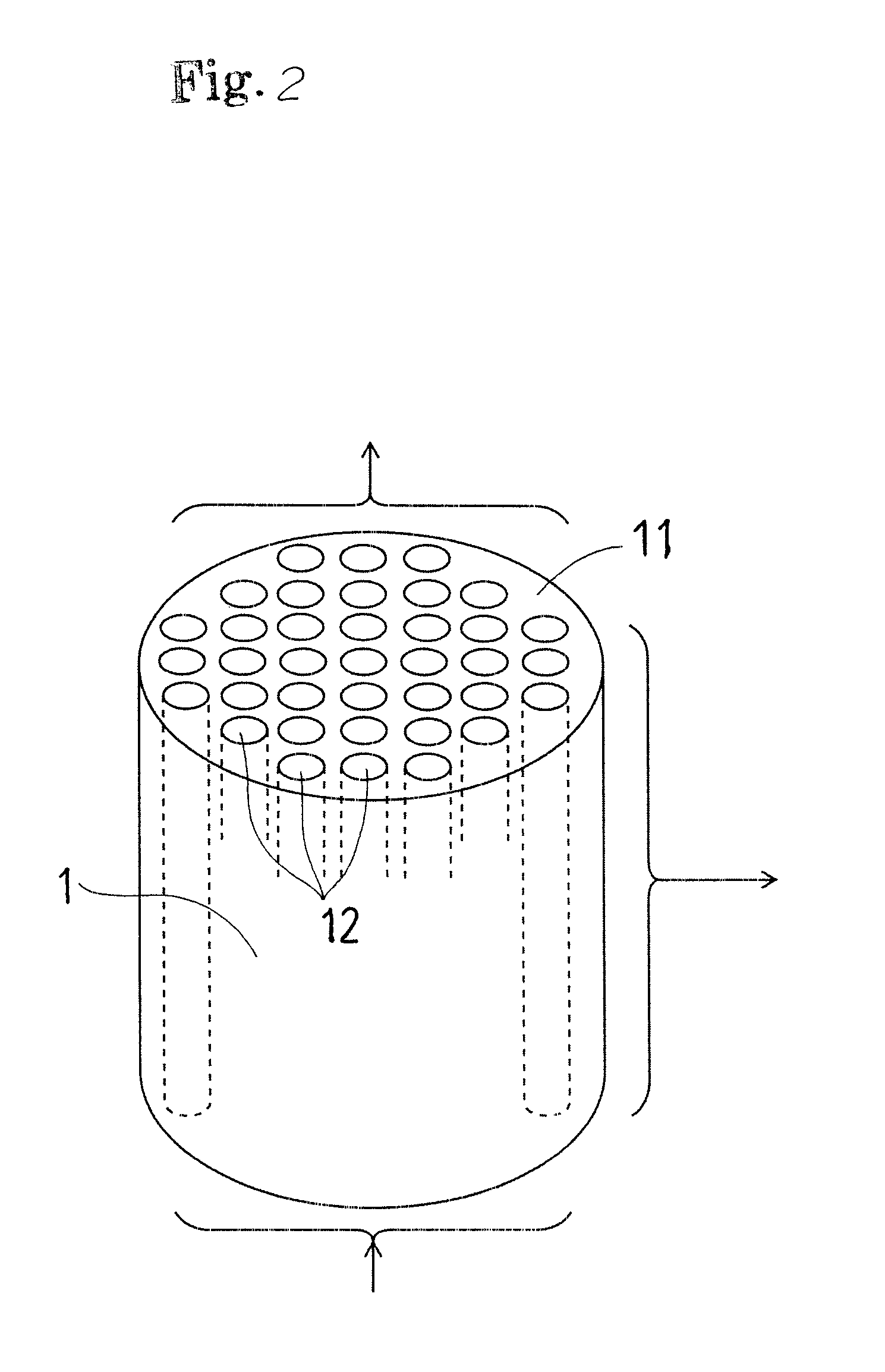
TECHNICAL FIELD[0001]The present invention relates to a method for membrane backwashing, and a backwashing apparatus.BACKGROUND ART[0002]A membrane filtration apparatus, such as is exemplified in FIG. 2, has a structure in which a membrane element 1, formed with a large number of filtration channels 12 arranged in a porous portion 11 so as to be parallel to one another, is accommodated in a casing 13, as shown in FIG. 4. The membrane filtration apparatus performs a filtration operation as follows. In a cross flow filtration method, raw water a is introduced into a primary inlet chamber 13a. The raw water a is then passed through the filtration channels 12, during which time it is filtrated by minute filtration pores within the porous portion 11 and the raw water then circulates via a primary outlet chamber 13b and an upper header pipe in the form of returned raw water b. The water that has been filtrated is then taken out from a header tube 14. In a dead end filtration method, the p...

Claims


Application Information

Patent Timeline
Patent Type & Authority Patents(United States)
IPC IPC(8): B01D71/02B01D65/06B01D63/06C02F1/44B01D65/02
CPCB01D63/066B01D2321/185B01D71/02B01D65/02B01D2321/04
Inventor KANAYA, SHINJIROAOKI, NOBUHIRO
Owner METAWATER CO LTD
Learn More