Wafer pads for fixed-spindle floating-platen lapping

a floating plate, fixed-spindle technology, applied in the direction of lapping machines, grinding heads, manufacturing tools, etc., can solve the problem of abrading debris being continuously flushed from the abraded surface of workpieces

Inactive Publication Date: 2014-02-11
DUESCHER WAYNE O
View PDF73 Cites 6 Cited by
  • Summary
  • Abstract
  • Description
  • Claims
  • Application Information

AI Technical Summary

Benefits of technology

[0041]The presently disclosed technology includes a fixed-spindle, floating-platen system which is a new configuration of a single-sided lapping machine system. This system is capable of producing ultra-flat thin semiconductor wafer workpieces at high abrading speeds. This can be done by providing a precision-flat, rigid (e.g., synthetic, composite or granite) machine base that is used as the planar mounting surface for at least three rigid flat-surfaced rotatable workpiece spindles. Precision-thickness flexible abrasive disks are attached to a rigid flat-surfaced rotary platen that floats in three-point abrading contact with the three equal-spaced flat-surfaced rotatable workpiece spindles. These abrasive coated raised island disks have disk thickness variations of less than 0.0001 inches (3 microns) across the full annular bands of abrasive-coated raised islands to allow flat-surfaced contact with workpieces at very high abrading speeds and to assure that all of the expensive diamond abrasive particles that are coated on the island are fully utilized during the abrading process. Use of a platen vacuum disk attachment system allows quick set-up changes where different sizes of abrasive particles and different types of abrasive material can be quickly attached to the flat platen surfaces.
[0046]Air bearing spindles are the preferred choice over roller bearing spindles for high speed flat lapping. They are extremely stiff, can be operated at very high rotational speeds and are frictionless. Because the air bearing spindles have no friction, torque feedback signal data from the internal or external spindle drive motors can be used to determine the state-of-finish of lapped workpieces. Here, as workpieces become flatter and smoother, the water wetted adhesive bonding stiction between the flat surfaced workpieces and the flat-type abrasive media increase. The relationship between the state-of-finish of the workpieces and the adhesive stiction is a very predictable characteristic and can be readily used to control or terminate the flat lapping process.
[0051]Resilient wafer pads can be used to minimize the effects of the abraded surfaces of the wafers not being precisely parallel to the platen abrading surface. When the platen is lowered into abrading contact with the workpieces, the resilient pads are compressed and the wafer assumes full flat-surfaced contact with the platen abrading surface. The wafers are then abraded uniformly across the full abraded surfaces of the wafers. Typically, the misalignment of the wafers and the platen is very small, less than 0.001 inches (25 microns). The resilient wafer pads can easily compensate for misalignments of this magnitude, and larger.
[0053]The wafer pads have the same nominal sizes as the wafer so abrasive polishing is uniform across the full surface of the wafers. Use of the same-sized wafer pads avoids the undesirable excessive abrasion at the outer flat-surfaced periphery of wafers that commonly occurs when wafers are polished using large-diameter rotating resilient abrasive slurry coated pads. In that polishing system, the stationary-position rotating wafers are thrust downward into the surface-depths of resilient moving CMP pads. Distortion of the resilient CMP pads at the periphery of the wafers causes the excessive abrading of the flat-surfaced periphery of the wafers.
[0054]The same types of chemicals that are used in the conventional CMP polishing of wafers can be used with this abrasive lapping or polishing system. These liquid chemicals can be applied as a mixture with the coolant water that is used to cool both the wafers and the fixed abrasive coatings on the rotating abrading platen This mixture of coolant water and chemicals continually washes the abrading debris away from the abrading surfaces of the fixed-abrasive coated raised islands which prevents unwanted abrading contact of the abrasive debris with the abraded surfaces of the wafers.

Problems solved by technology

The applied coolant water results in abrading debris being continually flushed from the abraded surface of the workpieces.

Method used


Image

  • Wafer pads for fixed-spindle floating-platen lapping
  • Wafer pads for fixed-spindle floating-platen lapping
  • Wafer pads for fixed-spindle floating-platen lapping

Examples


Embodiment Construction

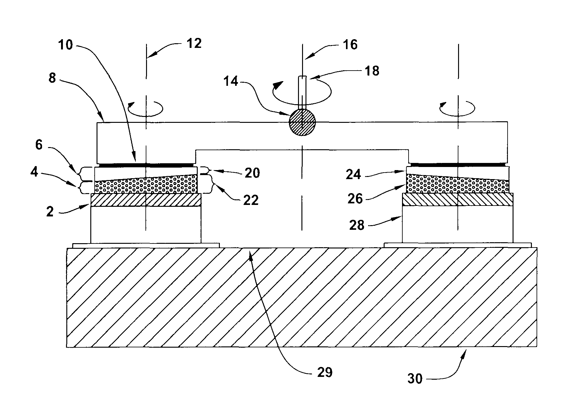
[0104]The fixed-spindle floating-platen lapping machines used for high speed flat lapping require very precisely controlled abrading forces that change during a flat lapping procedure. Very low abrading forces are used because of the extraordinarily high cut rates when diamond abrasive particles are used at very high abrading speeds. As per Preston's equation, high abrading pressures result in high material removal rates. The high cut rates are used initially with coarse abrasive particles to develop the flatness of the non-flat workpiece. Then, lower cut rates are used with medium or fine sized abrasive particles during the polishing portion of the flat lapping operation.

[0105]When the abrading forces are accurately controlled, the friction that is present in the lapper machine components can create large variations in the abrading forces that are generated by machine members. Here, even though the generated forces are accurate, these forces are either increased or decreased by mac...


PUM

PropertyMeasurementUnit
diameteraaaaaaaaaa
flatnessaaaaaaaaaa
flatnessaaaaaaaaaa

Abstract

Three rotary wafer abrasive lapping spindles having attached wafers are mounted on the flat surface of a granite lapping machine base. A flexible raised island abrasive disk is attached to the annular abrading surface of an abrading platen that is rotated at high speeds to flat lap, or polish, the exposed surfaces of the rotating wafers. Resilient wafer pads are used to minimize the effects of the abraded surfaces of the wafers not being precisely parallel to the platen abrading surface due to misalignment of the spindle tops. The resilient pads also compensate for two opposed flat surfaces of wafers not precisely parallel with each other. A mixture of the same types of chemicals that are used in the conventional CMP polishing of wafers with applied coolant water can be used with this abrasive lapping or polishing system to enhance abrading and to continually wash abrading debris from the wafers.

Description

CROSS REFERENCE TO RELATED APPLICATION[0001]This invention is a continuation-in-part of U.S. patent application Ser. No. 13 / 370,246 filed Feb. 9, 2012 that is a continuation-in-part of U.S. patent application Ser. No. 13 / 351,415 filed Jan. 17, 2012 that is a continuation-in-part of U.S. patent application Ser. No. 13 / 280,983 filed Oct. 25, 2011 that is a continuation-in-part of U.S. patent application Ser. No. 13 / 267,305 filed Oct. 6, 2011 that discloses subject matter that is novel and unobvious over the technical field-related technology disclosed in U.S. patent application Ser. No. 13 / 207,871 filed Aug. 11, 2011 that is a continuation-in-part of U.S. patent application Ser. No. 12 / 807,802 filed Sep. 14, 2010 that is a continuation-in-part of U.S. patent application Ser. No. 12 / 799,841 filed May 3, 2010, which is in turn a continuation-in-part of the U.S. patent application Ser. No. 12 / 661,212 filed Mar. 12, 2010. These are each incorporated herein by reference in their entirety.B...

Claims


Application Information

Patent Timeline
Patent Type & Authority Patents(United States)
IPC IPC(8): B24B7/22
CPCB24B37/26B24B37/107B24B7/228B24B37/30B24B7/22B24B37/245B24B41/047
Inventor DUESCHER, WAYNE, O.
Owner DUESCHER WAYNE O
Why Eureka
Try Eureka