Automatic method and system for measurements of bone density and structure of the hip from 3-D X-ray imaging devices

a technology of x-ray imaging and x-ray imaging device, which is applied in the field of 3d volumetric x-ray imaging, can solve the problems of loss of long-term precision, variability of bmd measurements of hips, and prior art bmd methods that are not applicable to the measurement of much different anatomy of hips, so as to achieve maximum precision and reduce operator time and effort

Active Publication Date: 2014-02-11
IMAGE ANALYSIS
View PDF62 Cites 27 Cited by
  • Summary
  • Abstract
  • Description
  • Claims
  • Application Information

AI Technical Summary

Benefits of technology

[0012]The embodiment disclosed herein is believed to be the first totally automated hip BMD measurement method from 3-D image sets. The method is further improved by using single or dual thresholding techniques with hybrid or phantom calibrated voxels. The segmentation methods being totally automatic reduce operator time and effort while providing maximum precision. For all of the reasons discussed above, automatic identification, segmentation and quantification of bone density in the hip provides important improvements and is very desirable in the clinical setting.
[0013]Methods are disclosed which provide totally automatic measurement of hip bone density and structure from 3-D volumetric X-ray imaging devices. The methods preferably use calibrated images for improved precision, but can operate without calibration. The number of interactions by the operator with the images can be zero. The reproducibility of measurements is improved since the operator's subjective judgment is essentially eliminated. The proximal femurs are located automatically and their boundaries are identified in 3-D space.

Problems solved by technology

The complicated 3-D anatomical shape, density and structure of the proximal femur make hip BMD measurements subject to variability and loss of precision with current methods.
Prior art BMD methods are not applicable to the measurement of the much different anatomy of the hip.
Operator decisions and interactions are known to vary over time and between operators resulting in a loss of long term precision.
Prior art methods have serious limitations in achieving the desired long term precision.
These reported methods still require manual interactions by the operator with the images.
This retains some elements of variability by the operator resulting in variable results and long term precision loss.
Since the CT numbers (HU units) are estimates of the X-ray attenuation coefficients of tissue relative to water, they fail to be truly quantitative for several reasons.
Such manual procedures are tedious and time consuming, as well as prone to error and non-reproducibility in exact positioning.
In addition, because many objects in the image, such as the trochanter or neck have complex shapes and irregular margins, a fixed geometry ROI or marker will cause errors, which can be quite large and variable and difficult to evaluate over long time periods.
Even though this significantly aids in locating and segmentation the bone regions, the operator, by manually placing the search marker on a 2-D representation of a complex 3-D object creates variations which reduce precision.
The operator must use judgment in placing the marks or ROIs, which can lead to errors and loss of reproducibility on follow up scans attributable to human error.

Method used


Image

  • Automatic method and system for measurements of bone density and structure of the hip from 3-D X-ray imaging devices
  • Automatic method and system for measurements of bone density and structure of the hip from 3-D X-ray imaging devices
  • Automatic method and system for measurements of bone density and structure of the hip from 3-D X-ray imaging devices

Examples


Embodiment Construction

[0029]A complete series of volumetric images making up an exam are analyzed by various computer algorithms as they are loaded into the computer. In a first preferred embodiment, an algorithm to automatically locate a calibration phantom and apply calibration of the images is completed in background mode without operator input.

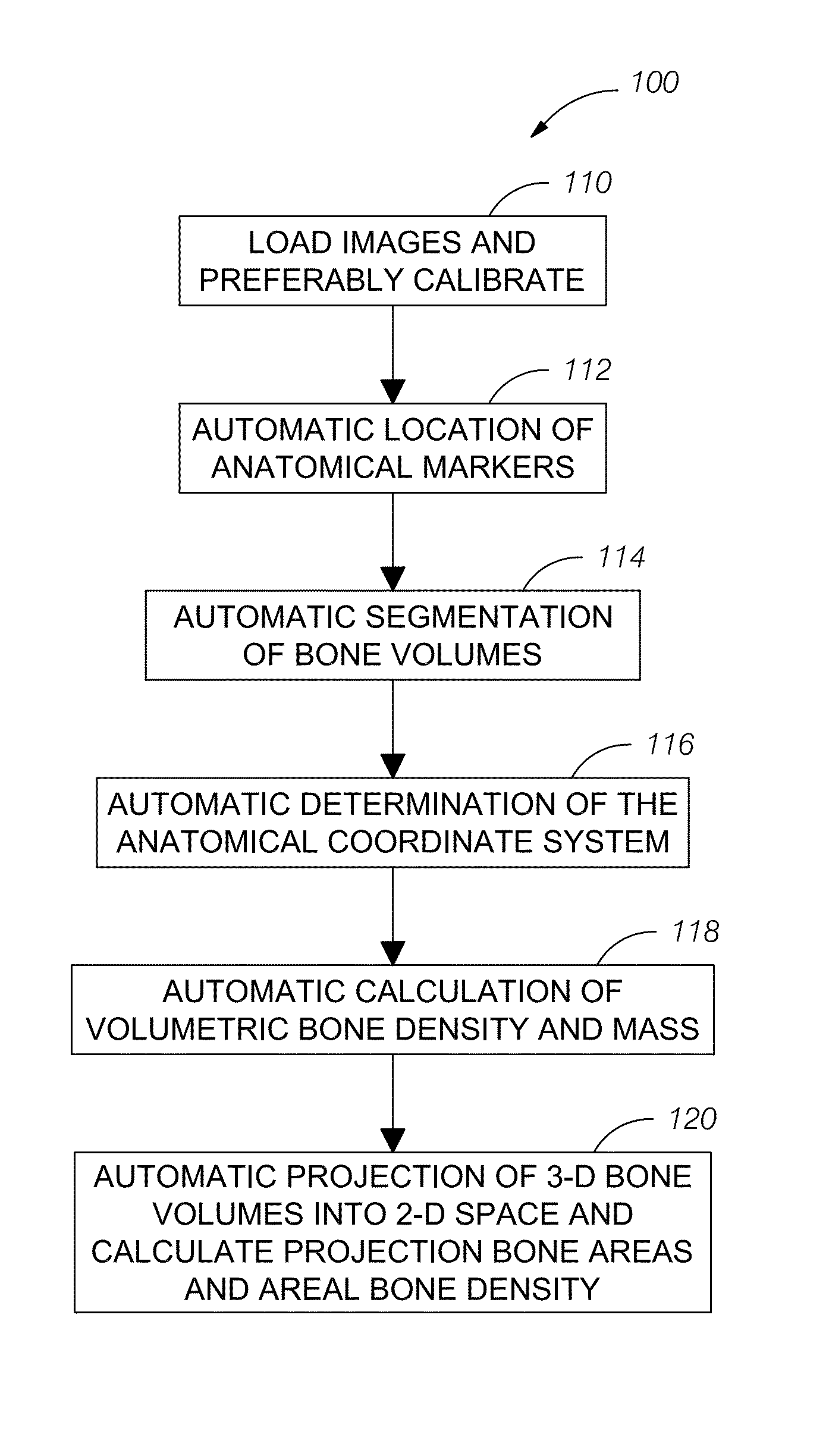
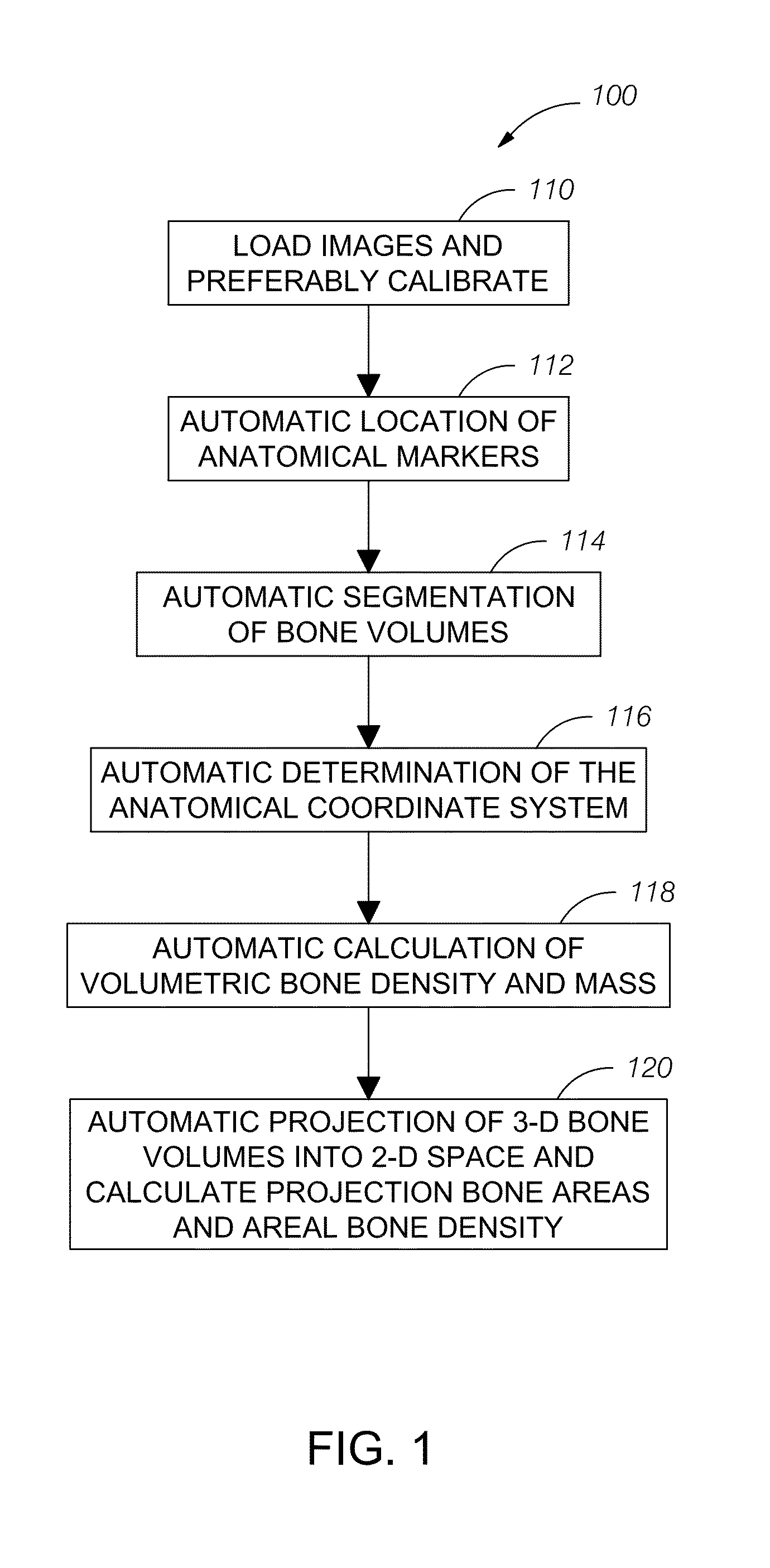
[0030]FIG. 1 illustrates a flowchart 100 of an overview of the automated methods to measure bone density of the proximal femur. In a step 110, a plurality (N) of images that include the femur are loaded. The images are generated by an imaging device shown schematically in FIG. 11 (described below). Preferably, but not necessarily, the images are calibrated with external phantoms or with the internal tissues of a subject. Preferably, the calibration occurs using the calibration equation disclosed, for example, in U.S. Pat. No. 6,990,922. For example, the calibration equation is determined by regression analysis. Through a series of automated algorithms, anatomic...


PUM


Abstract

A method uses a computer and software to measure bone density and structure of the proximal femur of the hip from a volumetric set of images containing pixels representing x-ray attenuation of the subject which are acquired with three-dimensional X-ray imaging devices. The method automatically locates anatomical markers of the hip without operator interaction, automatically positions regions of interest (ROIs) for measurement, automatically determines bone density measures of the ROIs, and automatically reports the results for individual subjects. Bone density measurements of ROIs include the integral bone of the total hip and neck as well as trabecular bone. The method automatically identifies a three-dimensional region-of-interest (ROI) volume which includes the hip, determines a three-dimensional coordinate system referenced to the anatomy of the subject, analyzes the ROI volume to identify voxels in the volume which satisfy defined criteria, and determines a measure of bone structure.

Description

RELATED APPLICATIONS[0001]The present application claims the benefit of priority under 35 USC §119(e) to U.S. Provisional Application No. 61 / 118,616, filed on Nov. 30, 2008, and to U.S. Provisional Application No. 61 / 118,619, filed on Nov. 30, 2008.BACKGROUND OF THE INVENTION[0002]1. Field of the Invention[0003]The present invention is in the field of 3-D volumetric X-ray imaging, and, in particular, is directed to an automated method to measure bone density and structure of the proximal femur without operator interaction.[0004]2. Description of the Related Art[0005]Several diagnostic 3-D X-ray imaging devices are used in medicine to measure bone density of the hip. These imaging devices to which this invention is directed provide a set of volumetric X-ray images acquired from multiple projection angles, which allow reconstruction of images in various planes. Such devices include: dual and single energy CT scanners, rotational G-arms, X-ray tomosynthesis and 3-D DXA (dual-energy X-r...

Claims


Application Information

Patent Timeline
Patent Type & Authority Patents(United States)
IPC IPC(8): G06K9/00
CPCA61B6/482G06T7/0083G06T7/00A61B6/505G06T2207/30008A61B6/032G06T2207/10081A61B6/025G06K9/00G06T7/12
Inventor ARNOLD, BEN A.XIANG, PING
Owner IMAGE ANALYSIS
Why Eureka
Try Eureka