Chromatic confocal scanning apparatus

a confocal scanning and chromatic technology, applied in the field of surface inspection apparatus, can solve the problems of insufficient optical resolution, poor pixel/spot resolution, and easy occlusion of the triangulation setup, so as to improve the accuracy of slit-based measurement, improve the field of view, and improve the effect of energy utilization

Active Publication Date: 2014-02-18
ASMPT SINGAPORE PTE LTD
View PDF6 Cites 4 Cited by
  • Summary
  • Abstract
  • Description
  • Claims
  • Application Information

AI Technical Summary

Benefits of technology

[0010]Thus, the invention seeks to provide an apparatus for scanning a surface of an object that has an increased field of view (“FOV”), better energy utilization and more accurate slit-based measurement as compared to the prior art.

Problems solved by technology

However, the triangulation setup is vulnerable to occlusion and shadows.
Moreover, due to the measurement range required by semiconductor packages like Ball Grid Array (BGA) packages, its pixel / spot resolution is typically poorer than 10 μm.
As such, there is insufficient optical resolution due to the required measurement range.
Unfortunately, the aforesaid chromatic confocal sensor can only inspect one single dot on the object surface at any one time.
As such, measurement of the whole of a three-dimensional surface is very time consuming and far from the high throughput required by the semiconductor industry.
Yet, owing to manufacturing difficulty, the Field of View (FOV) of commercial microscope objective lenses is very limited, especially those with large N.A. Therefore the inspection speed is also limited.
Furthermore, the N.A. of a circular objective lens is symmetrical and thus any out-of-focus light emerging from the slit which is projected on the object cannot be suppressed as in a conventional spot-scan confocal system.
Therefore, this will greatly affect the measurement accuracy.

Method used


Image

  • Chromatic confocal scanning apparatus
  • Chromatic confocal scanning apparatus
  • Chromatic confocal scanning apparatus

Examples


Embodiment Construction

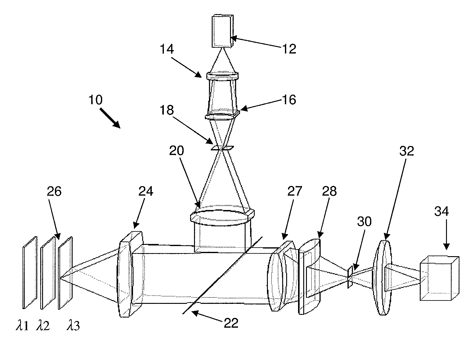
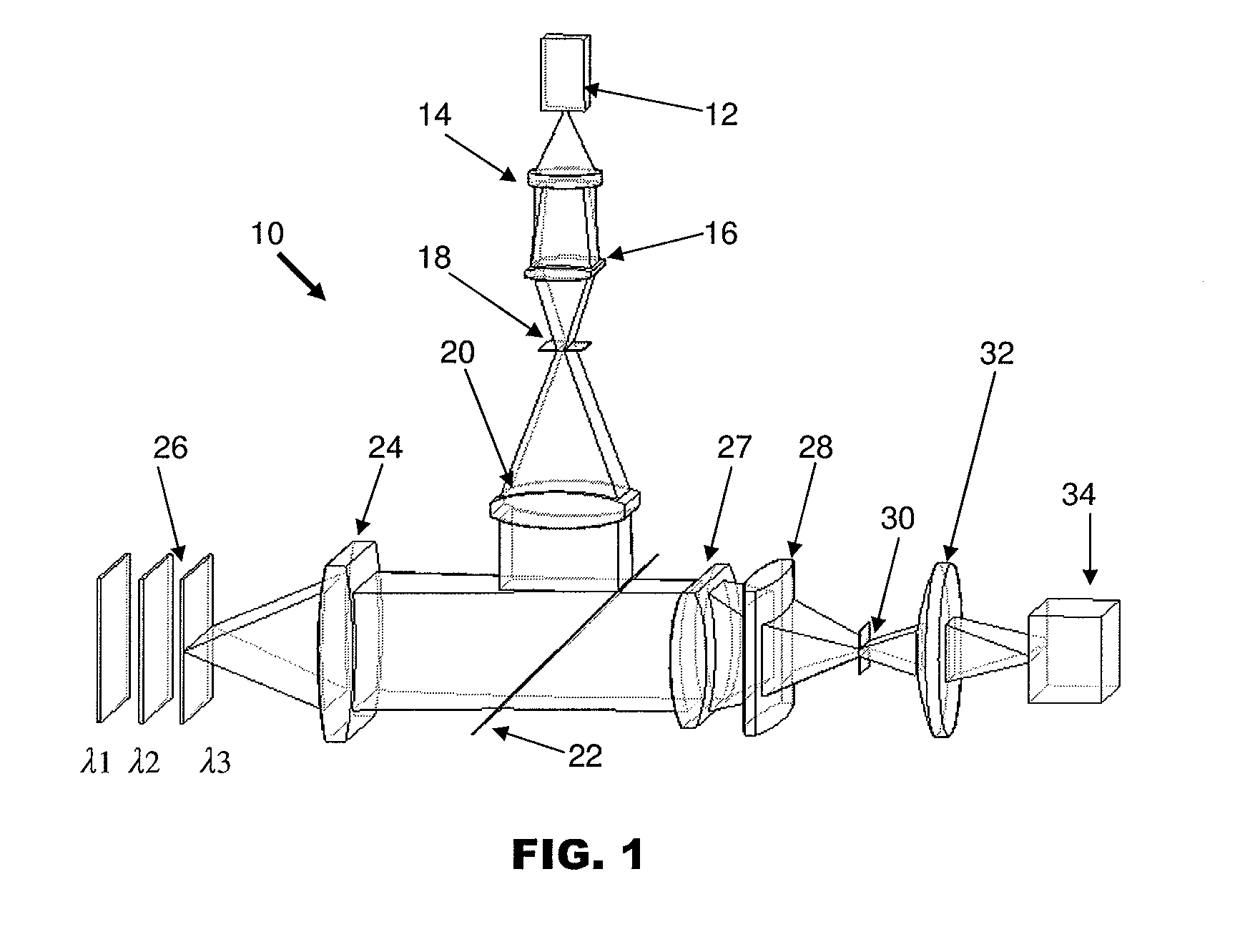
[0023]FIG. 1 is a schematic diagram showing a lens system 10 of a chromatic confocal scanning apparatus for measuring a surface 26 of an object according to the preferred embodiment of the invention. The lens system 10 comprises a light source 12 for producing light rays having multiple wavelengths for illuminating the surface. Light rays from the light source 12 comprising a plurality of wavelengths are passed through a first collimator 14 for making the light rays from the light source 12 parallel. Collimated light rays are transmitted through a cylindrical condenser 16 to a first screen with an open elongated slit 18 which allows a single strip of light rays to pass through the elongated slit 18. Thereafter, the strip of light rays is passed through an illuminating cylindrical achromatic lens 20 onto a beam splitter 22.

[0024]The beam splitter 22 directs the light rays from the light source 12 towards the surface 26 of the object to be measured. The light rays are converged and pr...


PUM


Abstract

A chromatic confocal scanning apparatus comprises a light source for producing light rays comprising a plurality of wavelengths, a first screen having an open elongated slit which allows a strip of light rays produced from the light source to pass through the slit and a cylindrical objective lens both to converge the light rays onto an object surface that is to be measured, and to image light rays reflected from the object surface. An intermediate cylindrical lens set converges a strip of light rays imaged from the cylindrical objective lens to pass through an open elongated slit comprised in a second screen, and a color sensor receives light rays which have passed through the slit of the second screen for determining a plurality of wavelengths of the said strip of light rays, to thereby construct a height profile of at least a portion of the object surface.

Description

FIELD OF THE INVENTION[0001]The invention relates to an apparatus for inspecting a surface of an object, and in particular for determining a height profile of the surface.BACKGROUND AND PRIOR ART[0002]Over the past few decades, demand for semiconductor devices has grown rapidly. Semiconductor manufacturers are often pressured into improvements in end-product quality, speed and performance, as well as improvements in manufacturing process quality, speed and performance. Machine vision has proven to be a very essential part of improving the productivity and quality of semiconductor production. There is a consistent drive for faster and more accurate machine vision systems for ever-higher semiconductor yields. Many high-density semiconductor packaging inspection applications require three-dimensional measurement capability. Correspondingly, the technical field of three-dimensional measurement and inspection for semiconductor devices, such as semiconductor wafers or substrates on final ...

Claims


Application Information

Patent Timeline
Patent Type & Authority Patents(United States)
IPC IPC(8): G01B11/24
CPCG01B11/24G01B2210/50G02B21/0024
Inventor DENG, JIANGWENZHANG, ZHUANYUNCHEN, FANG HANSZE, WUI FUNG
Owner ASMPT SINGAPORE PTE LTD
Why Eureka
Try Eureka