Cardiac valve repair system and methods of use

a technology for repair systems and mitral valves, applied in the field of repair systems for mitral valves and methods of use, can solve problems such as inability to solve solutions for repair of mitral valves, and achieve the effect of reducing the potential for movemen

Active Publication Date: 2014-02-25
BMEYE
View PDF32 Cites 304 Cited by
  • Summary
  • Abstract
  • Description
  • Claims
  • Application Information

AI Technical Summary

Benefits of technology

[0014]In accordance with another aspect of the present invention, the expandable stent of the replacement valve body may include a feature, e.g., a reduced diameter section, that is configured to engage the anchor component to reduce the potential for movement of the replacement valve body relative to the anchor. In still other embodiments, expansion of the expandable stent against the anchor may secure the anchor into engagement with the cardiac valve leaflets. In yet further embodiments, the double helix of the anchor may expand during deployment from a delivery configuration that facilitates insertion of a lower ring of the double helix into engagement with the ventricular surfaces of the leaflets and a deployed configuration wherein the double helix assumes an ovoid configuration that approximates the natural shape of the cardiac valve annulus. Alternatively, the double helix of the anchor transitions from a small diameter ring to a larger diameter ring, such that the anchor remodels the shape of cardiac valve annulus, e.g., from a substantially ovoid shape to a substantially circular shape.

Problems solved by technology

For example, whereas U.S. patent application Ser. No. US 2006 / 0265056 to Nguyen et al. describes a catheter-delivered aortic valve having a self-expanding stent that causes the valve to become anchored to the valve annulus, such a solution may not be feasible for repair of a mitral valve due to the possibility that the self-expanding stent may occlude the left ventricle outflow tract for the adjacent aortic valve.

Method used


Image

  • Cardiac valve repair system and methods of use
  • Cardiac valve repair system and methods of use
  • Cardiac valve repair system and methods of use

Examples


Embodiment Construction

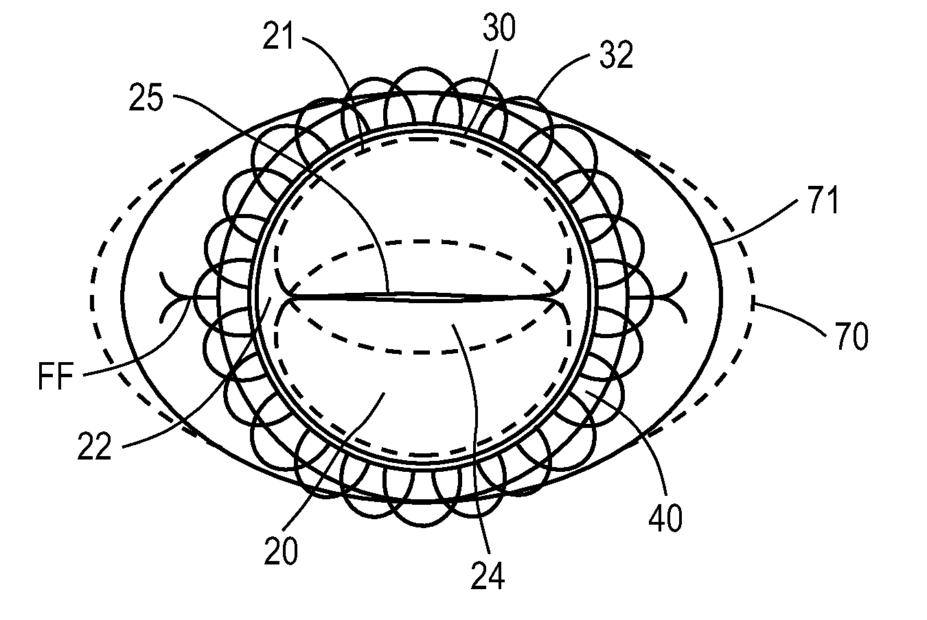
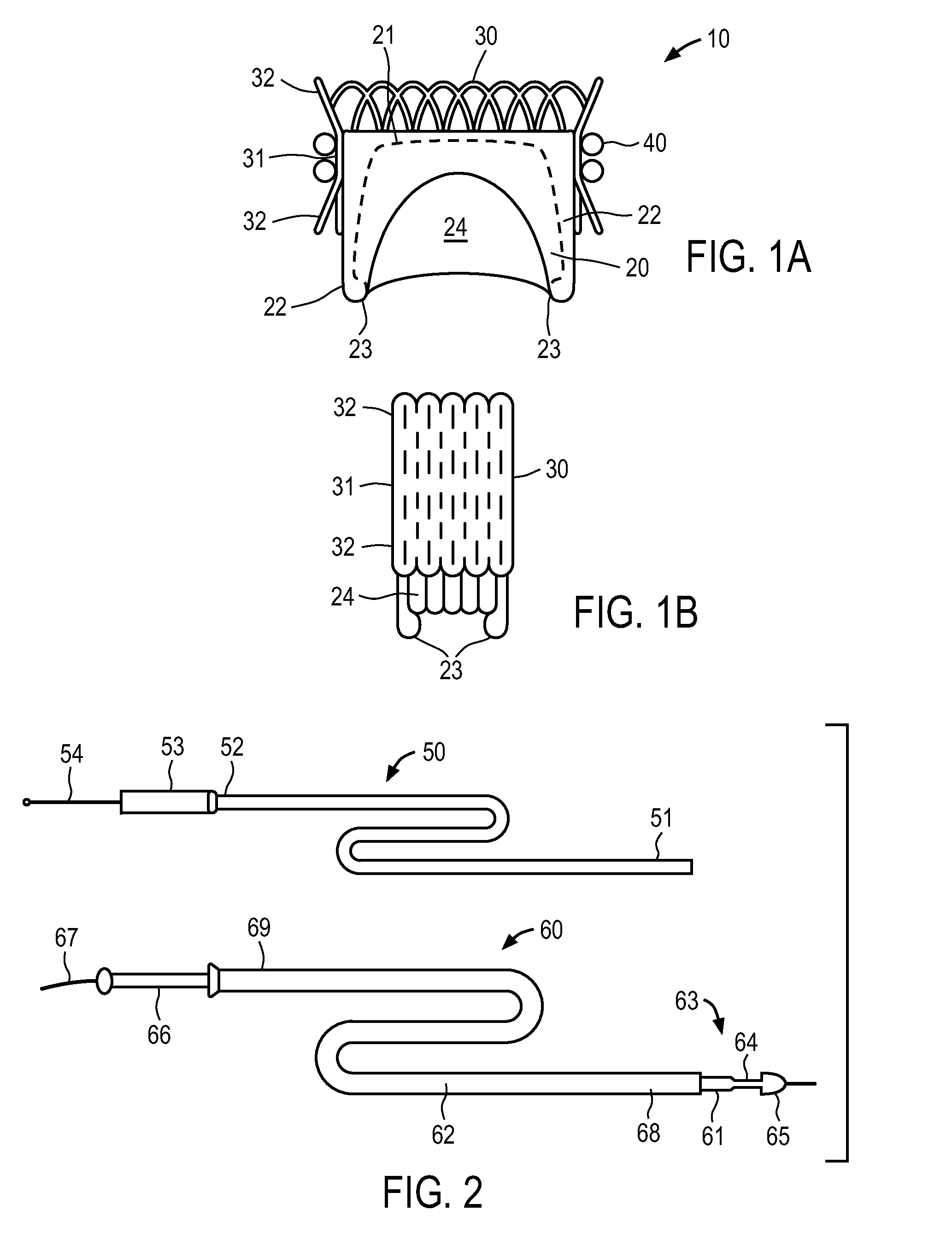
[0025]Referring to FIGS. 1A and 1B, an illustrative embodiment of a cardiac repair system constructed in accordance with the principles of the present invention is described. Illustratively, the cardiac valve is designed for replacement of a defective mitral valve, although it could be readily adapted for other cardiac valves. Replacement cardiac valve 10 includes animal tissue or synthetic valve body 20 mounted in expandable stent 30. Anchor 40 comprising a double helix of a metal alloy is shown engaged on the exterior of stent 30. Replacement cardiac valve 10 has an expanded, deployed state, shown in FIG. 1A, and a contracted delivery state, shown in FIG. 1B, such that the device may be disposed within a delivery catheter for transvascular or minimally-invasive surgical delivery. In FIG. 1B, anchor 40, which is separately delivered for this embodiment, is omitted.

[0026]For purposes of illustration only, expandable stent 30 comprises a self-expanding stent constructed using woven m...


PUM


Abstract

Methods and apparatus are provided for repairing or replacing a defective cardiac valve including an anchor having a double helix configured to engage the cardiac valve leaflets of a diseased or defective cardiac valve, and a replacement valve body disposed in an expandable stent configured to be disposed within the anchor so that the anchor limits expansion of the expandable stent. The expandable stent of the replacement valve body may be self-expanding or mechanically expanded, e.g., using a balloon catheter or catheter-based mandrel and the valve body may be formed of animal tissue or a synthetic fabric.

Description

I. FIELD OF THE INVENTION[0001]This application generally relates to apparatus and methods for performing transcatheter or minimally invasive repair or replacement of a cardiac valve, such as the mitral valve, by anchoring an expandable replacement valve body to the leaflets of an incompetent cardiac valve.II. BACKGROUND OF THE INVENTION[0002]In recent years a wide array of replacement cardiac valves have been proposed for treating cardiac valve diseases, such as valve regurgitation or stenosis. The human heart contains four valves that separate the atria from the lungs and ventricles: The tricuspid valve disposed between the right atrium and right ventricle, the pulmonary valve disposed between the right ventricle and the pulmonary artery, the bicuspid (or mitral) valve disposed between the left atrium and the left ventricle, and the aortic valve disposed between the left ventricle and the aorta. Each of these valves has a slightly different anatomy than the others, requiring diffe...

Claims


Application Information

Patent Timeline
Patent Type & Authority Patents(United States)
IPC IPC(8): A61F2/24
CPCA61F2250/006A61F2/2436A61F2230/0013A61F2230/0091A61F2/2418A61F2220/0016A61F2220/0033A61F2230/001A61F2230/0006A61F2210/0014A61F2250/0039A61F2250/0069A61F2250/0098A61F2220/0025A61F2/24A61F2/2427A61F2/2412A61F2/2442A61F2/2409A61F2/2433A61F2/243
Inventor SEGUIN, JACQUES
Owner BMEYE
Why Eureka
Try Eureka