Pressure vessel and method of use

a pressure vessel and pressure technology, applied in the direction of transportation and packaging, container discharging methods, packaging goods types, etc., can solve the problems of less than desired gaseous fuel mass, reduced driving range of vehicle users, and no means to compensate for under-filling problems, so as to reduce the amount of heat energy, reduce the temperature increase in gas, and minimize or eliminate the effect of gas density reduction

Active Publication Date: 2014-03-04
STEELHEAD COMPOSITES
View PDF8 Cites 17 Cited by
  • Summary
  • Abstract
  • Description
  • Claims
  • Application Information

AI Technical Summary

Benefits of technology

[0005]Some aspects of the invention alleviate the problem of under-filling by providing a gas storage device that can reduce the amount of heat energy generated during a gas filling process rather than simply relying on over-pressurizing the vessel. In particular, the gas storage device of the invention is designed to absorb heat energy that is generated during a gas filling process by utilizing a phase-change material (PCM). The use of PCM reduces the temperature increase in the gas and minimizes or eliminates reduction of the gas density during a gas fill process. The process of heat energy absorption by PCM is transparent to the filling process and the operation of the filling station.
[0007]One particular aspect of the invention provides a device comprising a vessel capable of storing gas under pressure. The vessel includes an orifice that can be used to fill the vessel with gas. The vessel also includes an inner surface that comprises a phase-change material. The presence of a phase-change material in the inner surface of the vessel reduces the temperature change within the interior of the vessel during a gas filling process. Typically, the phase-change material reduces the amount of temperature increase significantly compared to a similar gas storage vessel that does not have the phase-change material but is otherwise made of the same material. Typically, the PCM comprises a material that melts (i.e., changes phase) from solid to liquid at a certain temperature. The useful PCMs of the invention have a melting point in the range of from about 0° C. to about 80° C. typically from about 20° C. to about 50° C.
[0008]Other aspects of the invention provide a method for increasing the amount of gas filled in a vessel during a gas filling process. The method generally comprises providing a phase-change material on the inner surface of the gas storage vessel. The presence of phase-change material in the inner surface of the vessel substantially reduces the temperature and pressure increase during a gas filling process compared to a similar gas storage vessel that does not have a PCM. This reduction in the amount of temperature and pressure increase allows the vessel to be filled with a higher amount of gas compared to a similar vessel that does not have a phase-change material.
[0009]In some embodiments, the phase-change material reduces the temperature increase by at least 10° C., typically by at least 20° C. and often at least 30° C. in Type 4 tanks during a fast-fill process compared to a similar vessel that does not have the phase-change material.
[0010]Another aspect of the invention provides a device comprising a vessel capable of storing gas under pressure within an internal chamber. The internal chamber's surface comprises a phase-change material such that the presence of the phase-change material reduces the temperature change within the internal chamber during the compression of the gas. In some embodiments, the internal chamber comprises a bladder type vessel that stores gas under pressure.

Problems solved by technology

The problem of “under-filling” is a phenomenon whereby a vessel is filled with less-than-desired mass of gaseous fuel.
Under-filling of gaseous fuel during a filling process causes the vehicle user to experience a reduced driving range.
Currently there is no means to compensate for the under-filling problem by thermal management of the heat generated during the filling process.
Despite current understanding of the problems associated with the temperature increase during a gas-fill process, to date no adequate method or device is available that can reduce the amount of temperature increase during a gas-fill process, in particular during a fast-fill process.

Method used


Image

  • Pressure vessel and method of use
  • Pressure vessel and method of use
  • Pressure vessel and method of use

Examples


examples

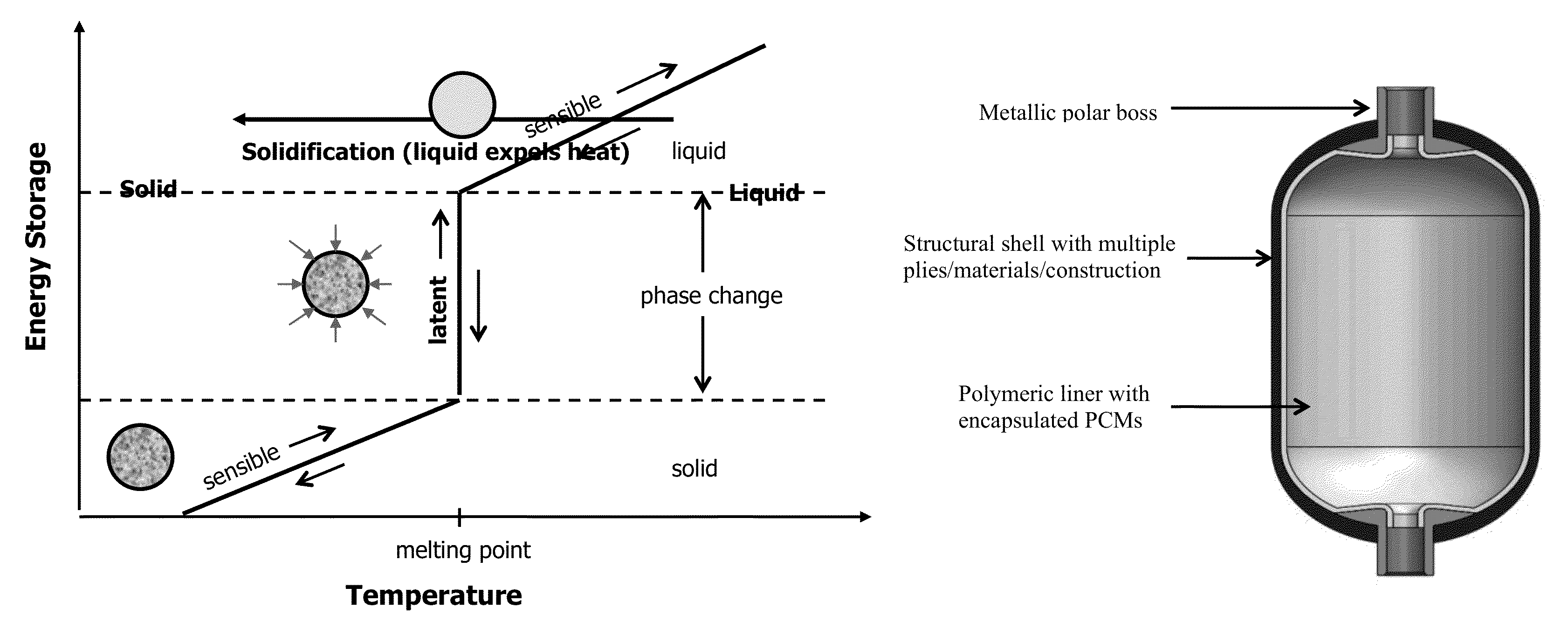
[0052]A Type 4 pressure vessel with PCM liner is produced using the following procedure. Microencapsulated PCM material in granular form is mixed in with polyethylene granules in pre-determined mix ratio and is fed to a rotomolding machine. The charge mixture is fed gradually into a heated hollow mold fitted with metallic polar bosses and is slowly rotated around two perpendicular axes causing the softened material to disperse and stick to the walls of the mold. Upon cooling the mold, the liner is demolded and removed from the rotomolding machine. At this stage, the liner includes a main body that comprises polymeric shell interdispersed with PCM and metallic polar bosses at one or both ends. The liner is mounted on a filament winding machine and wrapped with suitable thickness of composite raw material to provide structural strength. Once the composite shell is cured and hardened, the fabrication is complete for the Type 4 pressure vessel designed for gaseous storage. This vessel i...


PUM

PropertyMeasurementUnit
temperatureaaaaaaaaaa
melting pointaaaaaaaaaa

Abstract

The present invention provides a device and a method that minimizes or eliminates under-filling of a pressure vessel by integrating phase change material (PCM) within one or multiple component of the pressure vessel. In one particular embodiment, the inner surface of the pressure vessel comprises a PCM. During a gas-filling process, PCM reduces the rate and / or the amount of temperature increase. Reduction of the temperature increase in the pressure vessel increases the amount of gas filled during a gas-filling process.

Description

FIELD OF THE INVENTION[0001]The present invention relates to a device comprising a vessel that is capable of storing gas under pressure. In particular, the vessel has an inner surface that comprises a phase-change material. The phase-change material reduces the amount of temperature increase during a gas filling process compared to a similar vessel that does not have a phase-change material. This reduction in temperature increase allows for greater amount of gas to be filled at a given pressure.BACKGROUND OF THE INVENTION[0002]Unlike liquid fuel, which consistently holds about the same volume of fuel across a broad range of conditions, the amount of gaseous fuel inside a storage vessel depends on the pressure and temperature of the gas. The problem of “under-filling” is a phenomenon whereby a vessel is filled with less-than-desired mass of gaseous fuel. While filling the vessel rated for a certain pressure, the gas temperature rises during the filling process [1]. This temperature r...

Claims


Application Information

Patent Timeline
Patent Type & Authority Patents(United States)
IPC IPC(8): F17C13/00F17C1/12F17C1/00
CPCF17C2260/023F17C2203/068F17C1/12F17C13/002F17C1/005F17C1/00F17C2201/018F17C2203/0604F17C2203/0607F17C2203/0636F17C2203/066F17C2203/0663F17C2203/0697F17C2209/2118F17C2209/2145F17C2209/2154F17C2221/011F17C2221/012F17C2221/013F17C2221/014F17C2221/016F17C2221/017F17C2221/031F17C2221/033F17C2223/0123F17C2223/036F17C2225/0123F17C2225/036F17C2227/0157F17C2227/043F17C2260/025F17C2265/065F17C2270/0168F17C2270/0186F17C2270/02Y02E60/32
Inventor COORS, ANDREWMALLICK, KAUSHIK
Owner STEELHEAD COMPOSITES
Why Eureka
Try Eureka