
Piezoelectric oscillator

a technology of piezoelectric oscillator and oscillator, which is applied in the direction of oscillator, pulse technique, instruments, etc., can solve the problem of difficult high-frequency stabilization, and achieve the effect of early stabilization and high-frequency performan

Inactive Publication Date: 2014-03-11
NIHON DEMPA KOGYO CO LTD
View PDF18 Cites 7 Cited by
  • Summary
  • Abstract
  • Description
  • Claims
  • Application Information

AI Technical Summary

Benefits of technology

This configuration stabilizes the frequency at high frequencies at an early stage by aligning the resonance and oscillation frequencies, reducing sensitivity to adjustments and misalignment issues.

Problems solved by technology

However, the conventional piezoelectric oscillator has the following problems: as the frequency becomes higher, its wavelength becomes shorter, and for this, it is necessary to take into consideration the line length of a printed-circuit board, the line length from a resonator to a package, misalignment at the time of mounting a resonator, and the like; and moreover, the line lengths are changed due to those factors, which causes the frequency to deviate from a desired frequency and makes phase adjustment sensitive due to adjustment of the frequency, thereby making it difficult to highly stabilize the frequency.

Method used


Image

  • Piezoelectric oscillator
  • Piezoelectric oscillator
  • Piezoelectric oscillator

Examples


second embodiment

of a specific piezoelectric oscillator in the

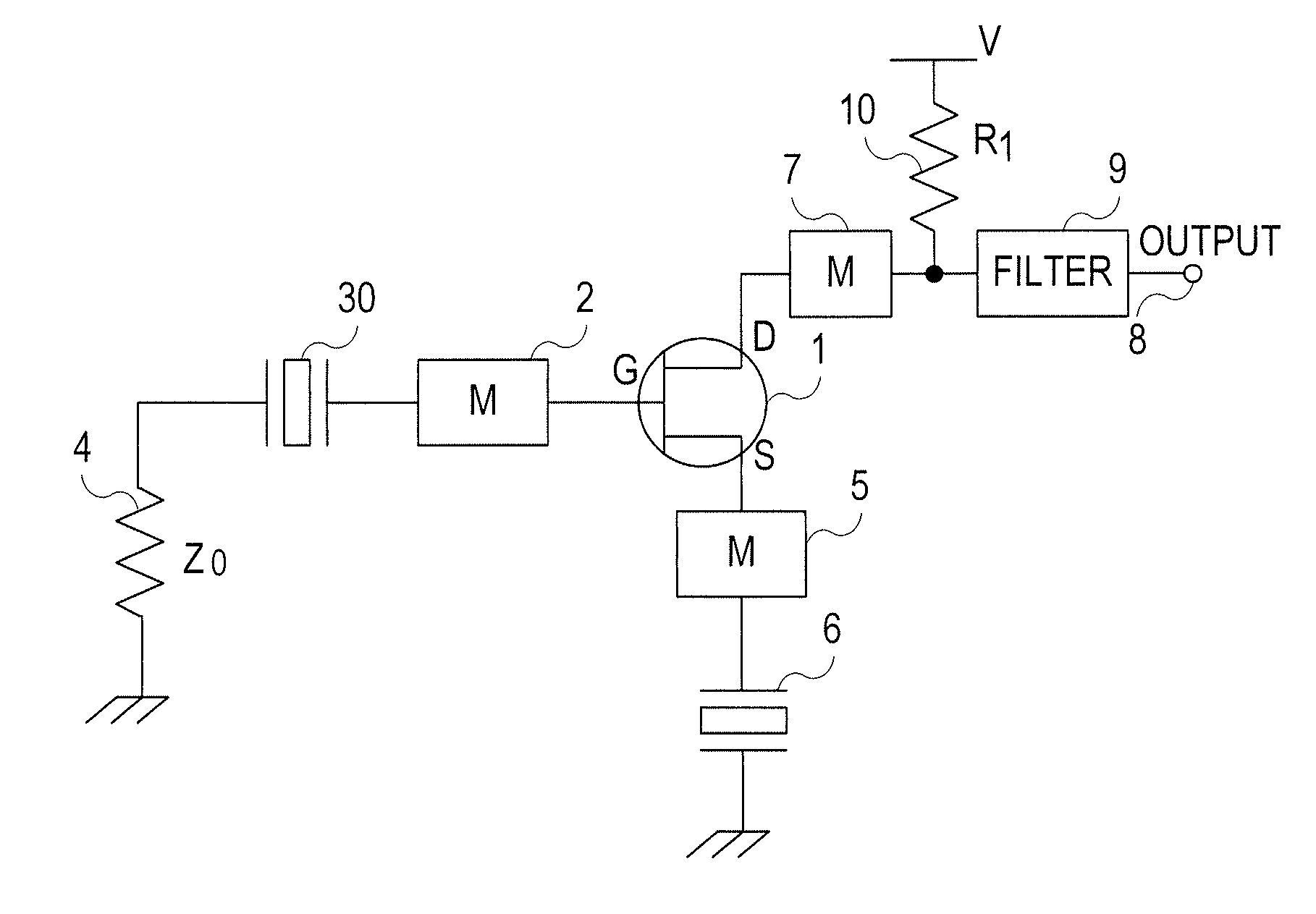
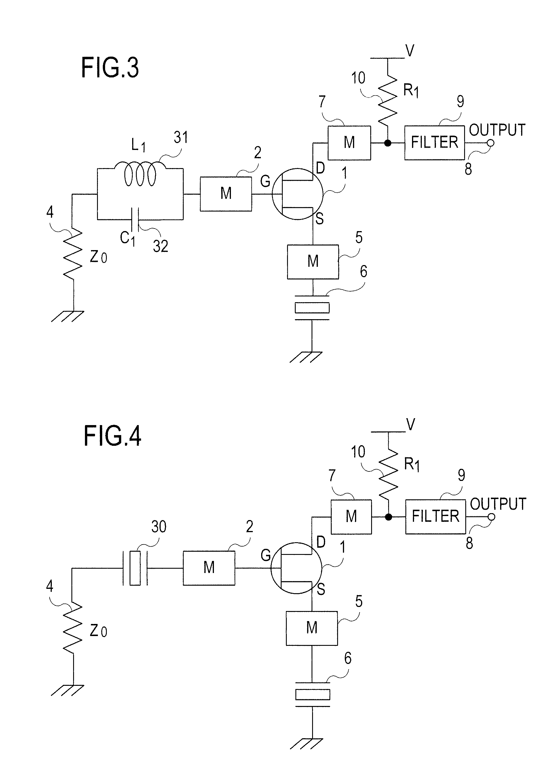
[0052]FIG. 4 is a circuit diagram illustrating Example 2 of a specific piezoelectric oscillator in the second embodiment.

[0053]FIG. 5 is a circuit diagram for a piezoelectric oscillator according to the third embodiment of the present invention.

[0054]FIG. 6 is a circuit diagram for a piezoelectric oscillator according to the fourth embodiment of the present invention.

[0055]FIG. 7 is a circuit diagram for a piezoelectric oscillator according to the fifth embodiment of the present invention.

[0056]FIG. 8 is a circuit diagram for a matching circuit 1.

[0057]FIG. 9 is a circuit diagram for a matching circuit 2.

[0058]FIG. 10 is a circuit diagram illustrating a case where a resonant circuit is a microwave circuit.

[0059]FIG. 11 is a circuit diagram for a simulation circuit.

[0060]FIG. 12 is views showing simulation results of oscillation starting time.

[0061]FIG. 13 is a circuit diagram for a conventional Colpitts crystal oscillator.

[0062]FIG. 14 is...


PUM


Abstract

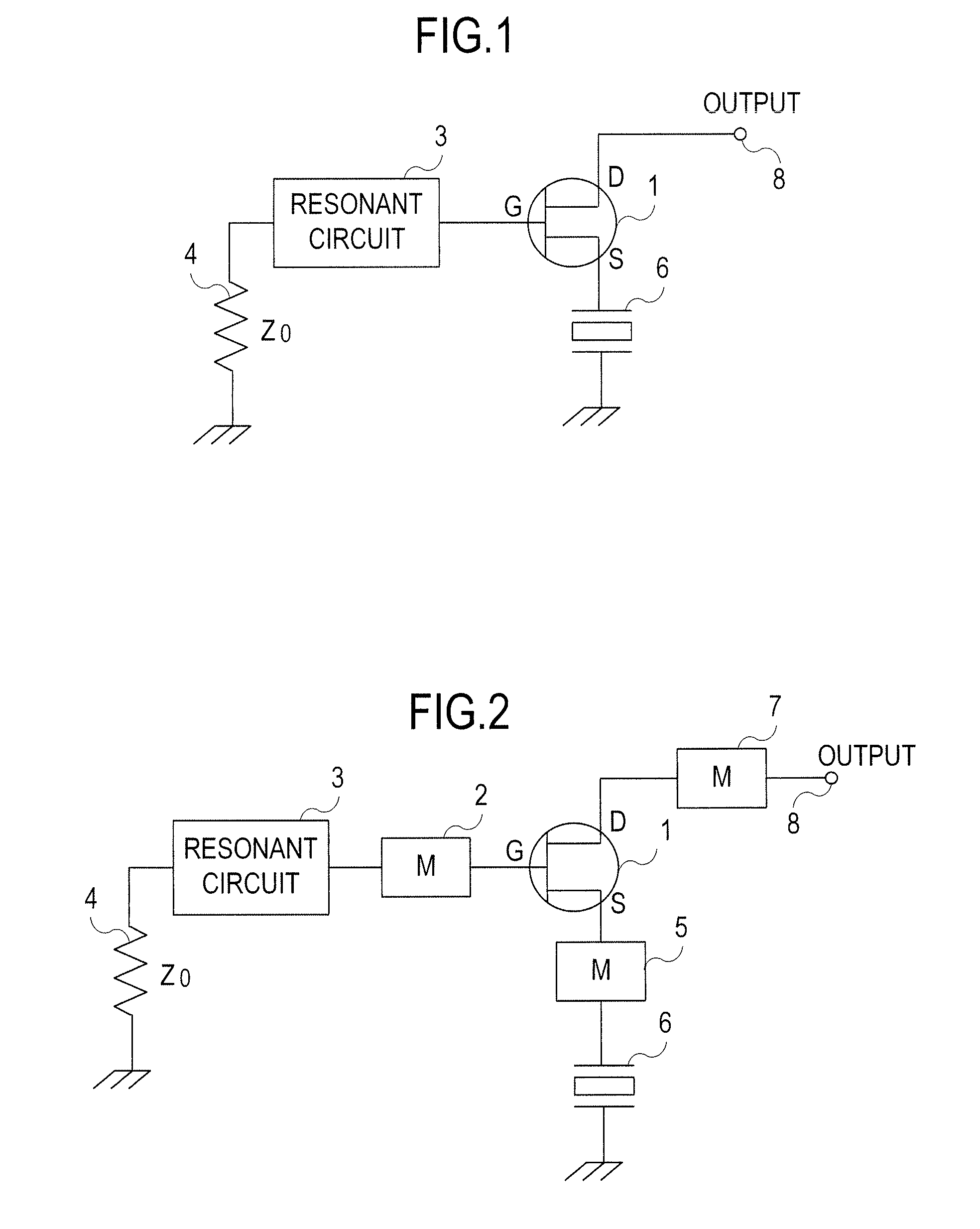
Provided is a piezoelectric oscillator to attain high-frequency performance and frequency stabilization with the use of reflection characteristics of a reflective element. A piezoelectric oscillator is configured such that: a resonant circuit is connected to a gate of a field effect transistor; an output terminal is connected to a drain and a power supply voltage V is applied to the drain; a piezoelectric resonator is connected to a source, as a reflective element; and a resonance frequency of the resonant circuit and an oscillation frequency of the piezoelectric resonator as a reflective element are set to substantially the same frequency, and further, the piezoelectric oscillator may be configured such that a first matching circuit is provided between the resonant circuit and the gate, a second matching circuit is provided between the drain and the output terminal, and a third matching circuit is provided between the source and the reflective element.

Description

[0001]This application has a priority of Japanese no. 2011-022346 filed Feb. 4, 2011, no. 2011-273840 filed Dec. 14, 2011, hereby incorporated by reference.BACKGROUND OF THE INVENTION[0002]1. Field of the Invention[0003]The present invention relates to a piezoelectric oscillator using a reflective element, and, more specifically, to a piezoelectric oscillator which attains high-frequency performance and frequency stabilization with the use of reflection characteristics of a reflective element.[0004]2. Description of the Related Art[Prior Art][0005]As a piezoelectric oscillator, there are a Colpitts circuit, a Pierce circuit, and the like circuits.[0006]A conventional oscillator has controlled its frequency by use of a circuit which oscillates by controlling the phase of a resonator.[0007]As to the conventional piezoelectric oscillator, the following describes a crystal oscillator circuit of the Colpitts circuit and a crystal oscillator circuit of an inverter circuit.[Colpitts Crysta...

Claims


Application Information

Patent Timeline
Patent Type & Authority Patents(United States)
IPC IPC(8): H03B5/36
CPCH03B5/364H03B5/362
Inventor HOSODA, TOMOYUKI
Owner NIHON DEMPA KOGYO CO LTD
Learn More