Measurement method and device for thread parameters

a measurement method and thread technology, applied in the direction of instruments, using electrical/magnetic means, electric/magnetic measuring arrangements, etc., can solve the problems of only achieving alignment, requiring absolute precision of operations, and precision and repeatability of measurements

Active Publication Date: 2014-03-25
TENARIS CONNECTIONS
View PDF23 Cites 2 Cited by
  • Summary
  • Abstract
  • Description
  • Claims
  • Application Information

AI Technical Summary

Benefits of technology

[0008]A main object of the present invention is to provide a method for accurate, automatically performed, non-contact inspection of threaded objects, in particular of oil pipe threads, especially of pins and boxes.
[0017]it allows absolute measurements to be performed on several threading parameters and tube features regardless of any misalignment between the threaded tube and the measurement apparatus,
[0018]detrimental contact between the object to be measured and the measurement apparatus is avoided thanks to the use of non-contact sensors, like laser sensors or other optical sensors,

Problems solved by technology

A main problem in performing the measurement operations for quality control is the precision and repeatability of measurements.
That document however has the disadvantage that it does not address explicitly the important problem of piece misalignment and therefore it requires an absolute precision of the operations when aligning the piece to be measured with the mechanical system coordinates.
This alignment can only be achieved when the piece is at the threading machine.
Measuring at the threading machine has several disadvantages; it adds costly time to the threading process by preventing the inspection and manufacturing process from running in parallel, it requires placing delicate optics and precise mechanical components in a hostile environment with cutting oil and strong vibrations present, and to some extent uses the same mechanical movement that has to be verified.
Once the piece has been removed from the lathe, this alignment is very difficult to achieve manually and consequently the system disclosed by that document only allows measurement of relative or local magnitudes, i.e. thread height by comparing contiguous crests and roots, whereas errors introduced by a piece misalignment are not “noticed” by that solution and in these cases they produce an insufficiently precise measurement.
It also does not address the measurement of important thread parameters such as taper, run-in, run-out, black crest, length of complete thread or specific process parameters such as taper profile, pitch linearity, Fourier mode decomposition of ovality, lathe plate misalignment, hook end angle severity to name just a few.

Method used


Image

  • Measurement method and device for thread parameters
  • Measurement method and device for thread parameters
  • Measurement method and device for thread parameters

Examples


Embodiment Construction

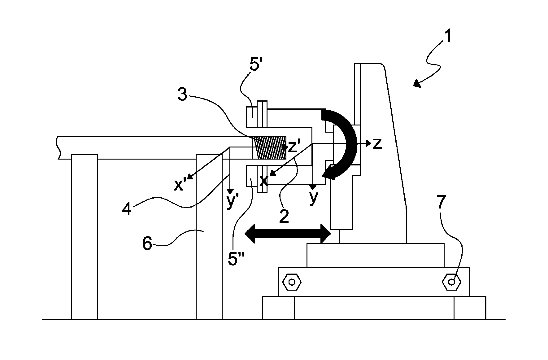
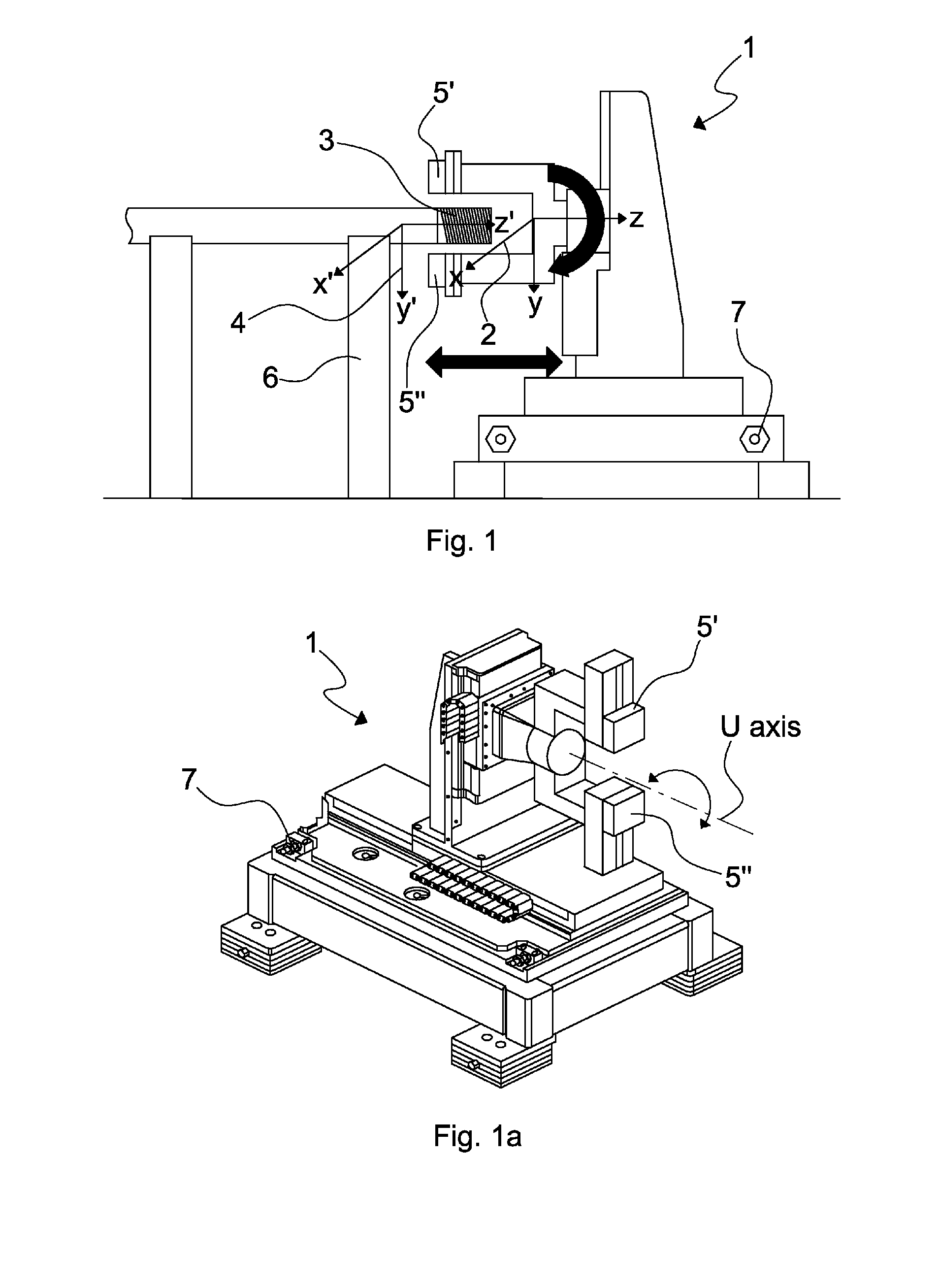
[0046]With particular reference to the FIGS. 1 and 1a, there is shown a scheme of an automatic thread inspection optical system based on laser displacement sensors, called in short hereafter “measurement” device 1, which has its own Cartesian reference system 2, defined by the orthogonal axes X, Y, Z. A threaded portion of a pin 3 to be measured is shown on the left of the figure. This pin has its own Cartesian reference system 4 defined by the orthogonal axes X′, Y′, Z′. In the FIG. 1 the pin is positioned far from the measurement device in a rest position on a bench 6.

[0047]In the following description of the invention, for the sake of simplicity, reference is made to a pin of an oil or gas pipe, however it is understood that the invention can have an application also for any other similar threaded objects, like screws or similar objects. When initial installation of the device is performed, a pin 3 is mounted on the measurement device 1 to perform the measurement operations accor...


PUM


Abstract

A measurement method for thread parameters for a threaded object (3), by means of a measurement device (1) defining a spatial reference system (X, Y, Z) incorporating an optical sensor (5) to retrieve the shape of the threaded object, and defining a spatial reference system (X′, Y′, Z′), the measurement device (1) having a computer to assemble a first matrix that describes the quadratic form representing the threaded object in the spatial reference system (X, Y, Z), thus providing the relationship between the two spatial reference systems. The method comprises the steps of:a) predefining at least one trajectory of the at least one optical sensor (5) on the threaded object, along which measurement points are selected such that the matrix evaluated on these values satisfies the condition that it has maximum rank,b) performing a first scanning operation by the at least one optical sensor (5) along said at least one trajectory and retrieving data of the predefined measurement points,c) feeding these data to the first matrix and calculating an axes transformation matrix relating the first spatial reference system with the second spatial reference system for defining the relative position of the threaded object with respect to the second spatial reference system,d) using the axes transformation matrix to convert all data retrieved from the second spatial reference system to the first spatial reference system.

Description

CROSS-REFERENCE To RELATED APPLICATIONS[0001]This application is a U.S. National Phase of PCT International Application No. PCT / EP2009 / 066309, filed Dec. 3, 2009, and published as WO 2010 / 063792 on Jun. 10, 2010, which claims priority to European Application No. 08170841.4, filed Dec. 5, 2008. The disclosure of both prior applications is incorporated by reference in their entirety and should be considered a part of this specification.FIELD OF THE INVENTION[0002]The present invention relates to a measurement method for threading, especially suited for threaded pipes used in the hydrocarbon industry and for similar threaded objects.BACKGROUND OF THE INVENTION[0003]In a thread manufacturing process such as that of a screw, bolt or of a threaded pipe it is necessary to verify that the geometrical dimensions of the piece comply with the tolerances set for the product. In addition, knowledge of the nature of the deviation from these tolerances can be used for feedback to the manufacturing...

Claims


Application Information

Patent Timeline
Patent Type & Authority Patents(United States)
IPC IPC(8): G01B11/24G06K9/00G01B11/08G06F19/00G01B21/10G01B13/08G01B7/12G01B5/08
CPCG01B11/2425
Inventor BONADEO, NICOLAS HERNANBERRA, SEBASTIANETCHEVERRY, JAVIER IGNACIO
Owner TENARIS CONNECTIONS
Why Eureka
Try Eureka