Cooking appliance

a technology for cooking appliances and water level sensors, which is applied in the field of cooking appliances, can solve the problems of inability of the water level sensor to detect factors, and achieve the effect of simple structure and cost reduction

Active Publication Date: 2014-04-15
SHARP KK
View PDF12 Cites 65 Cited by
  • Summary
  • Abstract
  • Description
  • Claims
  • Application Information

AI Technical Summary

Benefits of technology

[0026]As apparent from the above description, according to the cooking appliance of this invention, there can be realized a cooking appliance capable of detecting a halt of the steam generation function including emptiness of water in the water tank with a simple structure and without a water level sensor, and thus cutting down the cost.

Problems solved by technology

Moreover, in this cooking appliance, when the steam generation device stops steam generation due to factors (heater fault or pump fault) other than emptiness of water in the water tank, it is impossible for the water level sensor to detect the factors.

Method used


Image

  • Cooking appliance
  • Cooking appliance
  • Cooking appliance

Examples


first embodiment

[0038](First Embodiment)

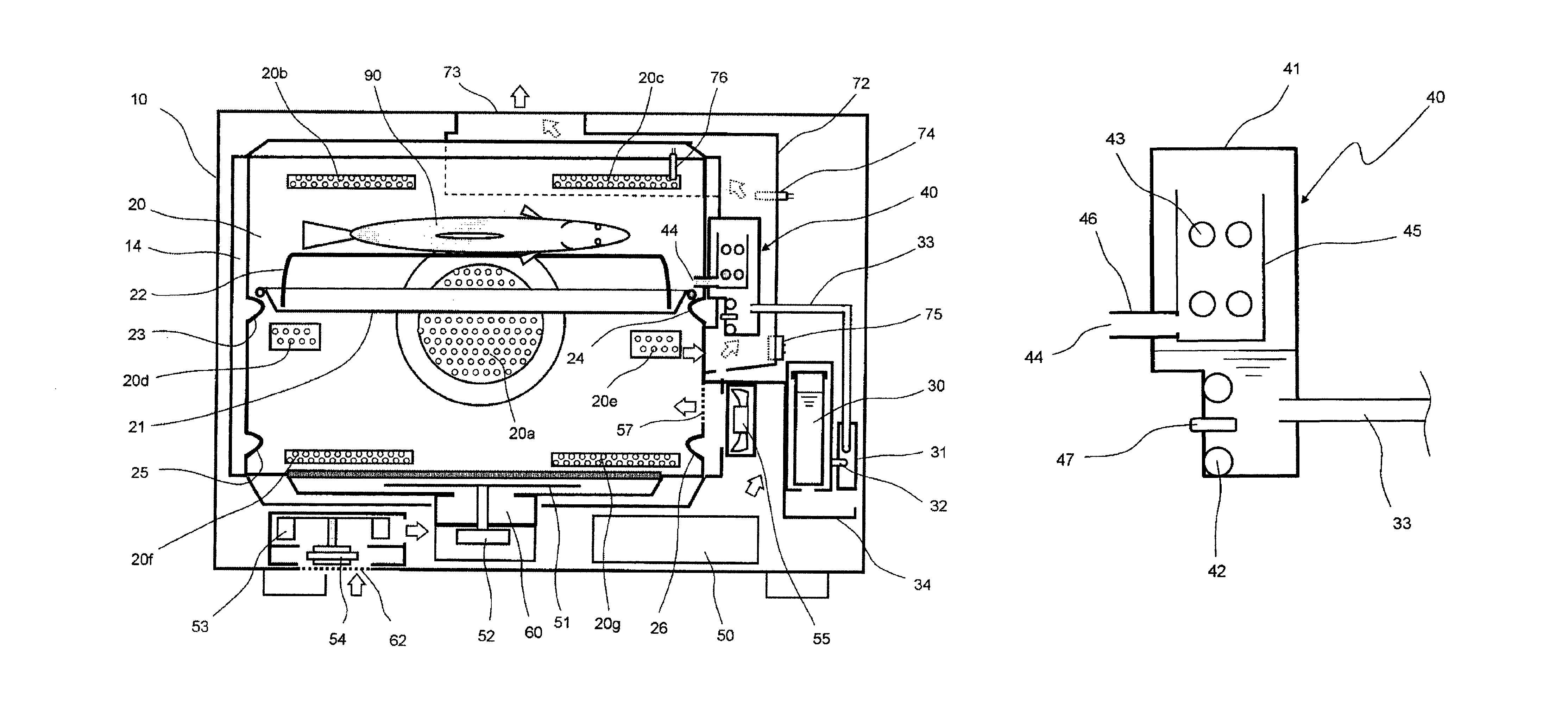
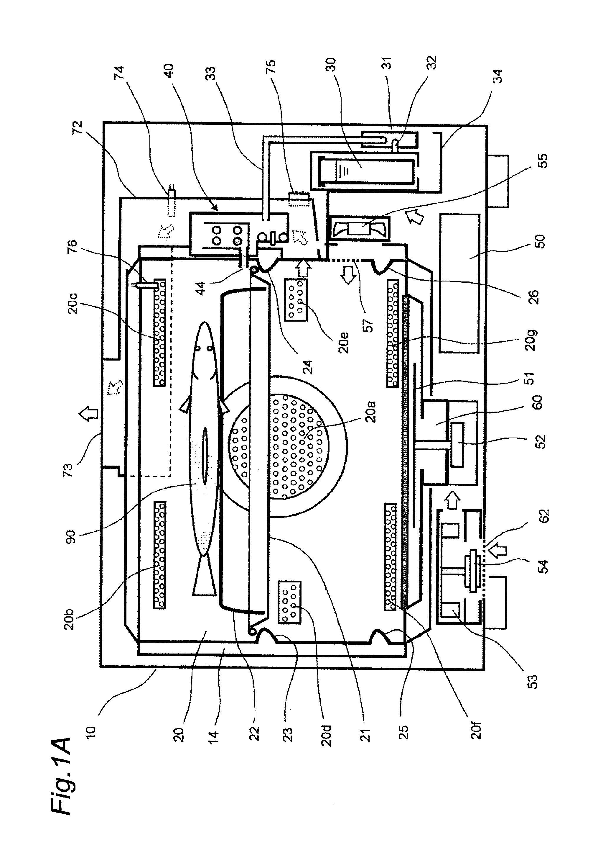
[0039]FIG. 1A is a schematic sectional view of a cooking appliance according to a first embodiment of the invention, as viewed from the front.

[0040]This cooking appliance, as shown in FIG. 1A, has a rectangular parallelopiped-shaped heating chamber 20 provided in a rectangular parallelopiped-shaped main casing 10. The heating chamber 20 has an opening on its front side, and is provided with a heat-shielding plate 14 of stainless steel on its side face, bottom face and top face.

[0041]A heat insulating material (not shown) is placed around the heating chamber 20 and inside a door 11 (shown in FIG. 2), so that inside of the heating chamber 20 is thermally insulated from its outside. Also, a square dish 21 made of stainless steel is placed in the heating chamber 20, and a gridiron 22 made of stainless steel wire for placing thereon a cooking object 90, which is to be cooked, is set on the square dish 21.

[0042]Upper square dish receivers 23, 24 and lower square di...

second embodiment

[0078](Second Embodiment)

[0079]FIG. 6 is a chart showing variations in output bit number of the exhaust humidity sensor 75 in response to turn-on and -off of the steam generation heater 42 during oven cooking using superheated steam in a cooking appliance according to a second embodiment of the invention. The cooking appliance of the second embodiment is similar in construction to the cooking appliance of the first embodiment except operation of the control unit 100, and therefore FIGS. 1A, 1B and 2 are referenced also in this case.

[0080]In FIG. 6, the horizontal axis represents time (minute) and the vertical axis represents output bit number of the exhaust humidity sensor 75. In this second embodiment, an output bit number of zero of the exhaust humidity sensor 75 represents an absolute humidity of the indoor air level, and larger bit numbers represent increases in absolute humidity with increased moisture in the exhaust.

[0081]In this cooking appliance of the second embodiment, in ...

third embodiment

[0093](Third Embodiment)

[0094]A cooking appliance according to a third embodiment of the invention is described below. The cooking appliance of the third embodiment is similar in construction to the cooking appliance of the first embodiment except operation of the control unit 100, and therefore FIGS. 1A, 1B and 2 are referenced also in this case.

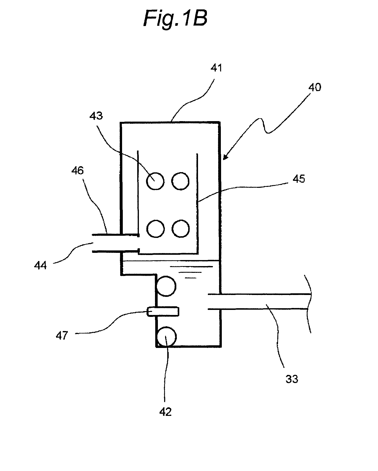
[0095]In steam cooking using steam in the cooking appliance of the third embodiment, the heater control unit 100b of the control unit 100 turns off the steam generation heater 42 when the temperature of the steam generation box 41 detected by the steam-generation-box temperature sensor 47 has exceeded an upper-limit temperature (e.g., 120° C.), and turns on the steam generation heater 42 when the temperature of the steam generation box 41 has lowered below a lower-limit temperature (e.g., 105° C.) in off state of the steam generation heater 42. It is noted that the upper-limit temperature and the lower-limit temperature may be set as approp...


PUM


Abstract

Disclosed is a cooking appliance provided with: a water tank (30) disposed inside a main case (10); a steam-generation device (40) that generates steam by heating water supplied from the water tank (30); a heating chamber (20) to which steam from the steam-generation device (40) is supplied; an exhaust duct (72), provided inside the main case (10), for expelling exhaust from inside the heating chamber (20) to outside the main case (10); an exhaust temperature sensor (74) that measures the temperature of the exhaust air inside the exhaust duct (72); and a steam-generation decision unit that, upon cooking in which steam is supplied from the steam-generation unit (40) into the heating chamber (20), uses information on a physical quantity (the exhaust temperature measured by the exhaust temperature sensor (74)), which indirectly indicates whether there is water in the steam-generation device (40), to decide whether or not to halt steam generation, including the case in which the water tank (30) is out of water.

Description

TECHNICAL FIELD[0001]The present invention relates to a cooking appliance.BACKGROUND ART[0002]In some types of conventional cooking appliances, water supplied from within a water tank is heated by a steam generation device to generate steam, and the generated steam is supplied to a heating chamber (see, e.g., JP 2009-41822 A (PTL 1)).[0003]This type of cooking appliance includes a water level sensor with a plurality of different-in-length electrodes combined together. By detecting which ones among the detection-use electrodes of the water level sensor are submerged in water, a water level within the water tank is detected, where with none of the detection-use electrodes submerged in water, it is decided that no water is present.[0004]However, this cooking appliance has a problem that the cost increases because of a complicated structure of the water level sensor. In this cooking appliance, a space for the water level sensor is necessitated in proximity to the water tank causing the ...

Claims


Application Information

Patent Timeline
Patent Type & Authority Patents(United States)
IPC IPC(8): H05B6/64A47J27/04A21B1/00
CPCF24C15/327
Inventor SAKANE, YASUAKIUEKI, TOSHIAKI
Owner SHARP KK
Why Eureka
Try Eureka