Highly integrated non-inductive LED driver

a non-inductive led driver, high-integration technology, applied in the direction of electric variable regulation, process and machine control, instruments, etc., to achieve the effect of avoiding flicker

Active Publication Date: 2014-04-15
TECHN CONSUMER PRODS
View PDF13 Cites 42 Cited by
  • Summary
  • Abstract
  • Description
  • Claims
  • Application Information

AI Technical Summary

Benefits of technology

[0036]Summarizing, the first closed loop feedback control system provides the control of the luminance of the LEDs over a range of zero to 100 percent; and the second closed loop feedback control system provides the control of a dynamic load across the output of the full wave diode bridge to effect a holding current through the triac dimmer to eliminate flickering.

Problems solved by technology

Any presence of inductance in the contemplated circuit is due to parasitic presence of inductance in non-ideal components.

Method used


Image

  • Highly integrated non-inductive LED driver
  • Highly integrated non-inductive LED driver
  • Highly integrated non-inductive LED driver

Examples


Embodiment Construction

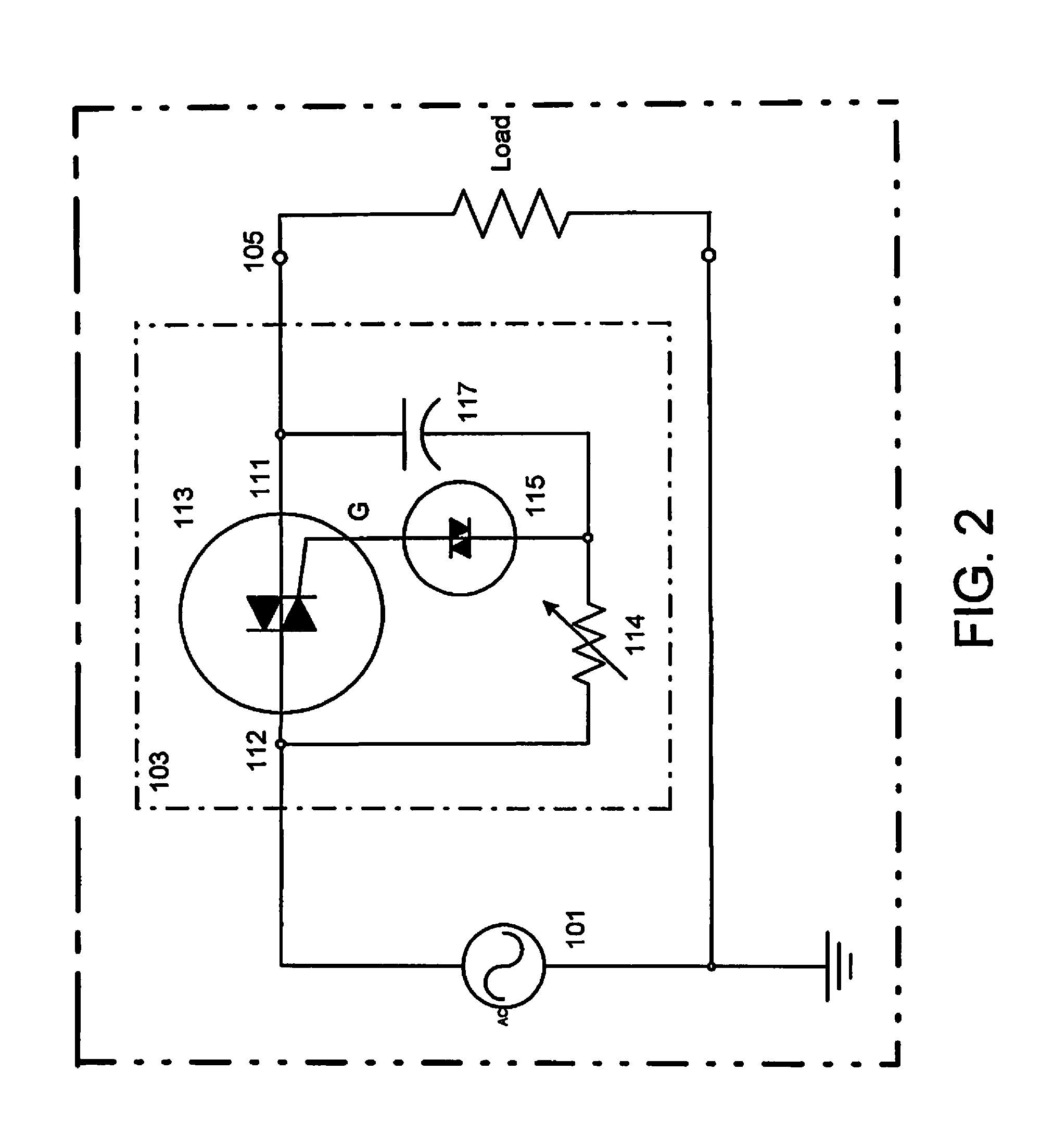
[0043]Referring now to the drawings in detail, FIG. 2 is a schematic diagram showing the basic triac dimming circuit in accordance with a first embodiment of the present invention.

[0044]The object of the phase controlled triac is to provide an inexpensive phase controlled circuit that will attain stable operation, accompanied by exceptional regulation against line and load variations, and to provide a precise open loop feedback control circuit. The principal features are shown in more detail in FIG. 5.

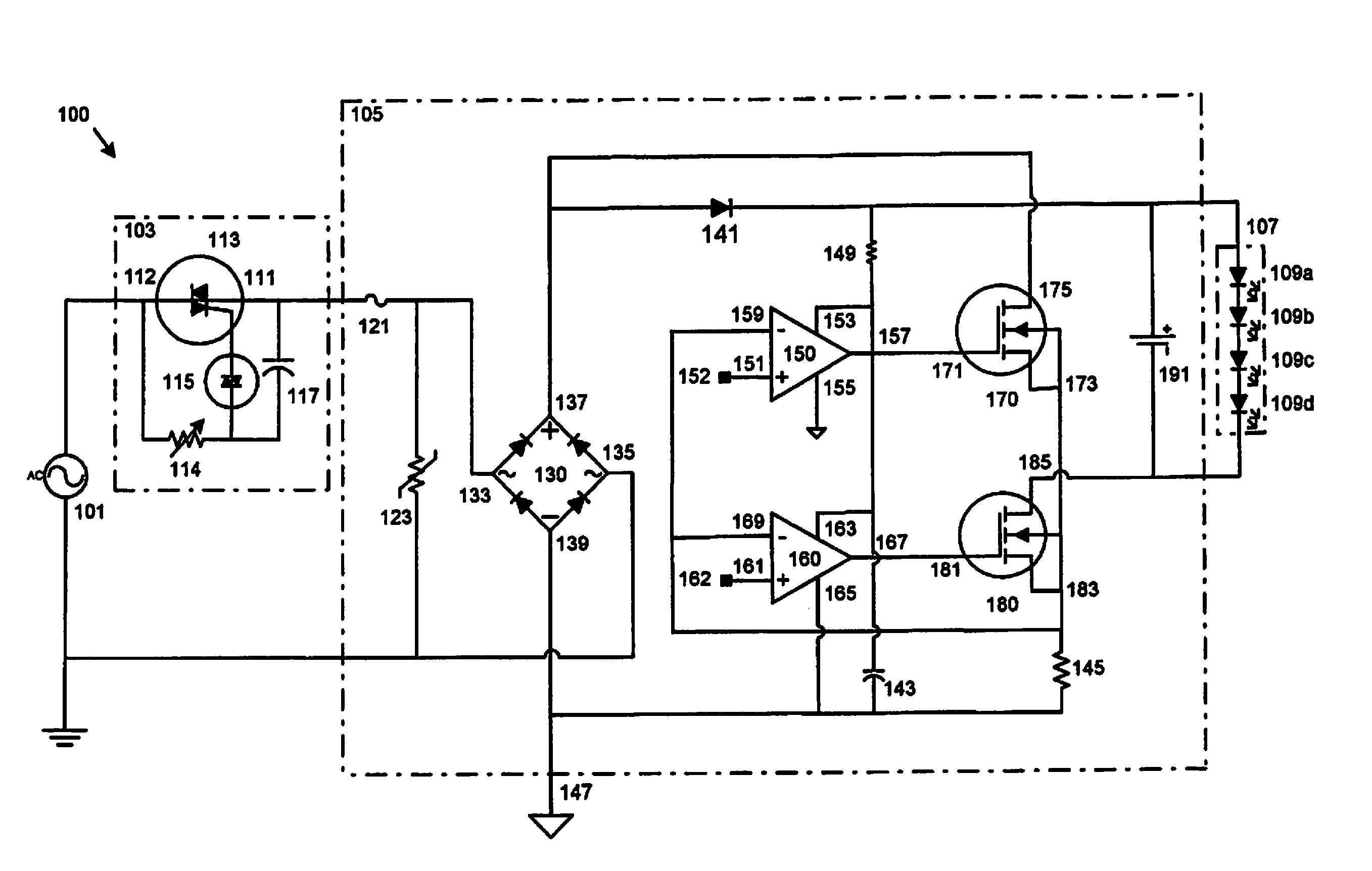
[0045]FIG. 3, a block diagram, shows the highly integrated non-inductive LED driver 100 utilizing serially connected low current LEDs that are operated by the driver circuit; the plurality of LEDs can attain 0-100% flicker-free, dimming and yet have compact size, high efficiency, high power factor, and still yet maintain a low cost.

[0046]Also shown in FIG. 3, are two closed loop feedback control systems; the first control system provides the basic luminance control system that is capab...


PUM


Abstract

An inductorless LED driver powers a string of low current LEDs. A phase controlled triac dimmer, serially connected to a full-wave rectifier circuit, performs as an LED current and triac holding current control element. The output of the full-wave rectifier circuit is divided into two circuit paths; the first path provides power to drive a string of serially-connected low-current LEDs, and the second path connects to a dynamic load, which supplies a holding current that flows through the triac dimmer. There are two feedback control systems; the first regulates the luminance of the LEDs; the second regulates the triac holding current to eliminate lamp flicker.

Description

FIELD OF INVENTION[0001]The present invention relates to semiconductor lighting devices, and more particularly to low current Light Emitting Diode (LED) lighting systems as used in conventional AC dimming circuits; the electronic driver circuits are used to power and control the light output of the LEDs.[0002]A lighting system utilizing serially connected low current LEDs that are operated by the driver circuit as disclosed herein, can achieve 0-100% flicker-free dimming and yet have compact size, high efficiency, high power factor, and still maintain a low cost.BACKGROUND OF THE INVENTION[0003]Semiconductor lighting systems that include the now familiar LED, are growing rapidly in popularity and success. Semiconductor lighting presents a number of advantages over more common lighting systems, such as incandescent and fluorescent lighting systems; they are more energy efficient than incandescent lamps, and they exhibit significantly greater lamp life than either incandescent or fluo...

Claims


Application Information

Patent Timeline
Patent Type & Authority Patents(United States)
IPC IPC(8): H05B39/00H05B41/00H05B37/00
CPCH05B33/0812H05B41/00H05B37/00Y02B20/345H05B39/00H05B45/395H05B45/3575Y02B20/30
Inventor CHEN, TIMOTHYBOYLE, JOHN
Owner TECHN CONSUMER PRODS
Why Eureka
Try Eureka