Transmissive display apparatus, mobile object and control apparatus

a display apparatus and mobile object technology, applied in static indicating devices, instruments, transportation and packaging, etc., can solve the problems of increasing the angle dependency of the reflective film, the inability to display the overall screen brightly, and the foregoing methods, so as to achieve uniform display, increase wavelength dependency and angle dependency of the hologram, and increase the effect of diffraction efficiency

Inactive Publication Date: 2014-04-15
PANASONIC CORP
View PDF22 Cites 16 Cited by
  • Summary
  • Abstract
  • Description
  • Claims
  • Application Information

AI Technical Summary

Benefits of technology

[0020]With the method of Japanese Patent Publication No. 2751436, the diffraction efficiency of the hologram needs to be approximately 100% in order to diffract the light transmitted through the front face of the windshield so as to prevent it from reaching the viewpoint direction, and thereby prevent the generation of a double image. Light that is not diffracted by the hologram will be transmitted as is, and cause a double image. As the diffraction efficiency is increased, the wavelength dependency and angle dependency of the hologram will increase, and uniform display becomes difficult. In other words, similar to the case of using an optical interference film, when a hologram having a high diffraction efficiency relative to the incidence angle at the center of the screen is used, the diffraction efficiency will deteriorate at the top and bottom of the screen, and the double image prevention effect will deteriorate.
[0022]As described above, it was difficult to inhibit the rear face reflected light and prevent the generation of double images while maintaining a high transmittance of the windshield and causing the stray light to be unobtrusive.
[0023]One non-limiting and exemplary embodiment provides a transmissive display apparatus, a mobile object and a control apparatus capable of preventing the generation of double images while maintaining a high transmittance of the display area.

Problems solved by technology

However, the foregoing methods entailed the following problems.
S60-124532, since the reflected wavelength width of the optical interference film needs to be extremely narrow in order to ensure a high transmittance, the angle dependency of the reflective film will increase, and it is difficult to display the overall screen brightly.
H2-141720, the angle of installing the windshield becomes restricted in order to match the incidence angle to the windshield with the Brewster's angle in relation to the viewpoint position, and there is a problem in that this method is not compatible with car models of various designs.
As the diffraction efficiency is increased, the wavelength dependency and angle dependency of the hologram will increase, and uniform display becomes difficult.

Method used


Image

  • Transmissive display apparatus, mobile object and control apparatus
  • Transmissive display apparatus, mobile object and control apparatus
  • Transmissive display apparatus, mobile object and control apparatus

Examples


embodiment 1

[0040](Embodiment 1)

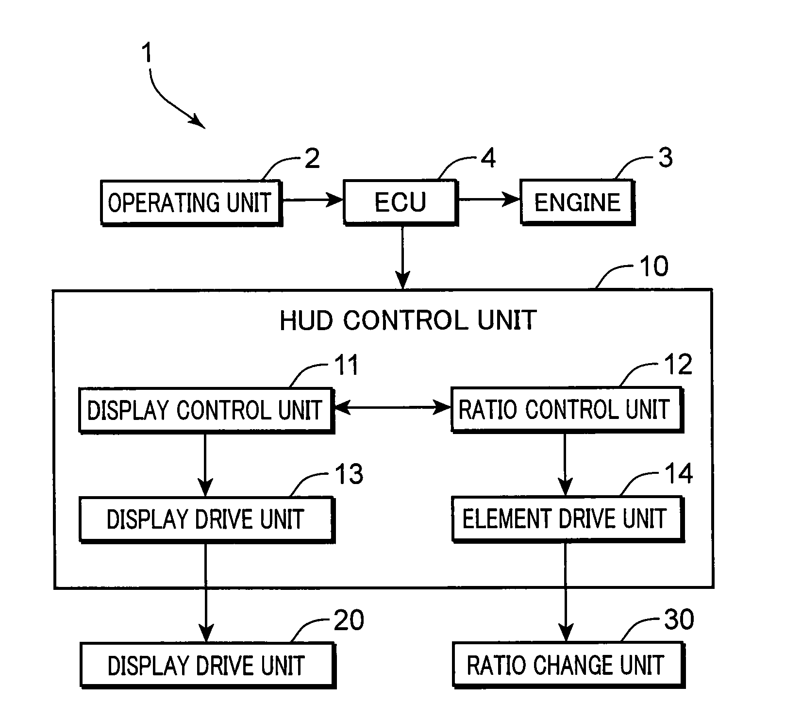
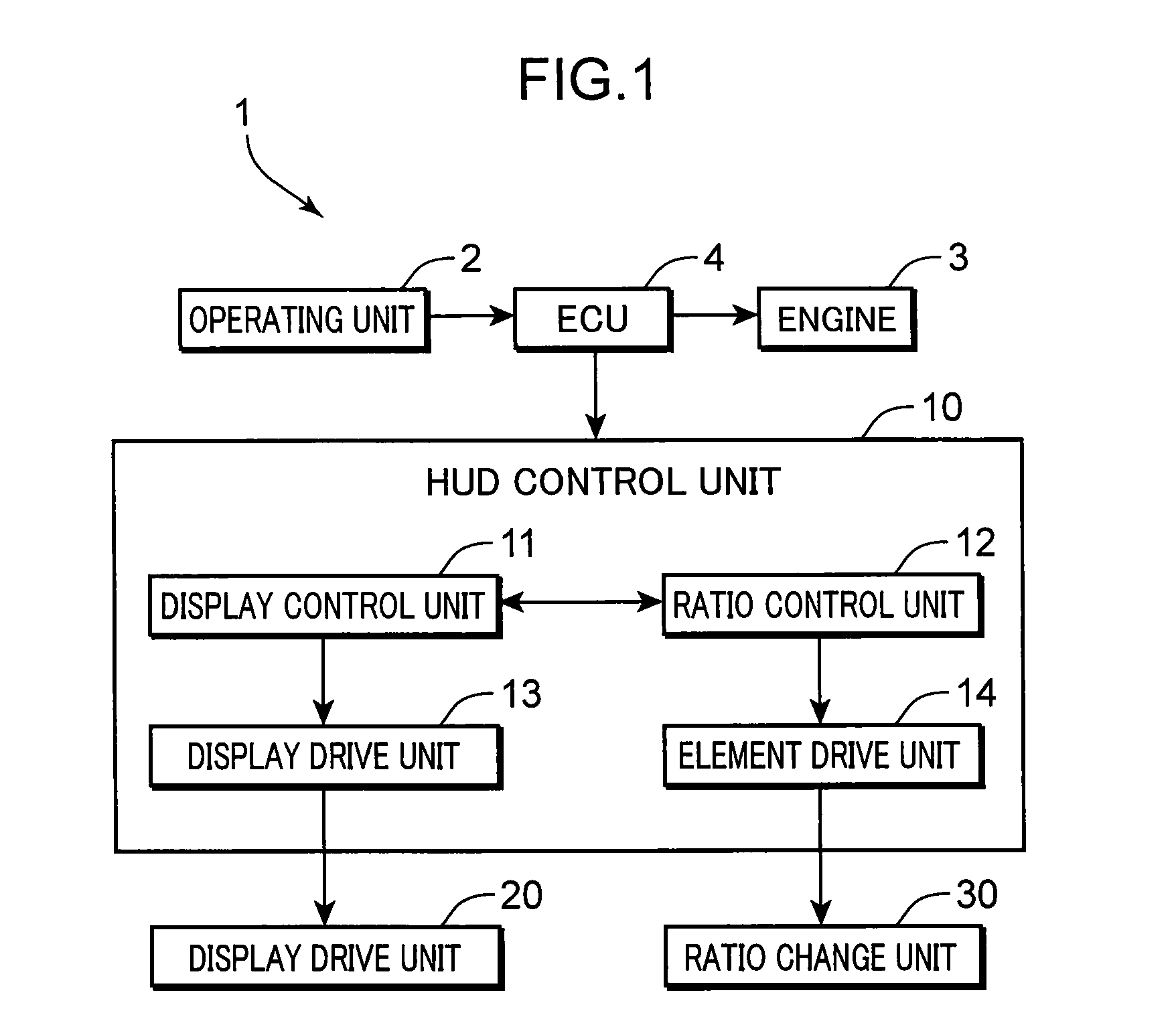
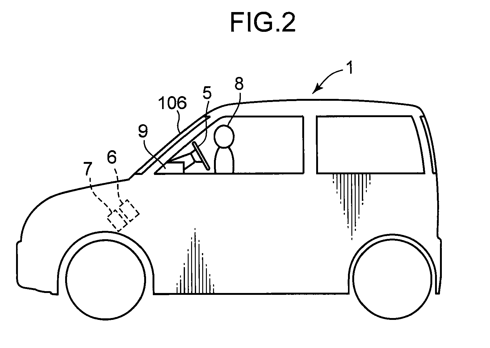
[0041]FIG. 1 is a block diagram showing an electrical configuration of a vehicle equipped with a head-up display (HUD) in Embodiment 1. FIG. 2 is a diagram schematically showing the foregoing vehicle. FIG. 3A and FIG. 3B are diagrams schematically showing the configuration of the HUD in Embodiment 1. FIG. 4 is a timing chart showing the operation of the HUD in Embodiment 1.

[0042]The vehicle 1 comprises an operating unit 2, an engine 3, an electronic control unit (ECU) 4, an HUD control unit 10, a display unit 20, and a ratio change unit 30. The HUD control unit 10 includes a display control unit 11, a ratio control unit 12, a display drive unit 13, and an element drive unit 14. The operating unit 2 includes, for instance, a steering wheel 5, a brake pedal 6, and an accelerator pedal 7. The operating unit 2 outputs, to the ECU 4, operation signals according to the operation of a driver 8. The engine 3 generates a drive force for moving the vehicle 1 according to t...

embodiment 2

[0069](Embodiment 2)

[0070]FIGS. 6A, 6B are diagrams schematically showing the configuration of the HUD in Embodiment 2. As with Embodiment 1, FIG. 6A shows the display period (first state), and FIG. 6B shows the non-display period (second state).

[0071]In Embodiment 2, as the ratio change unit 30 (FIG. 1), a switching light-shielding element 32 is used in substitute for the switching diffractive element 31. The switching light-shielding element 32 is an element in which the transmittance changes based on the application of voltage and, for example, is a multilayer body in which a composite membrane where metal particles are dispersed in the mother phase of the dielectric material is sandwiched by transparent conductive films, and is an element that is configured so that the transmittance will decrease when voltage is applied.

[0072]By using this kind of switching light-shielding element 32, in FIG. 6A, the ratio control unit 12 controls the element drive unit 14, and, in a state where...

embodiment 3

[0077](Embodiment 3)

[0078]FIGS. 7A, 7B are diagrams schematically showing the configuration of the HUD in Embodiment 3. As with Embodiment 1, FIG. 7A shows the display period (first state), and FIG. 7B shows the non-display period (second state).

[0079]In Embodiment 3, as the ratio change unit 30 (FIG. 1), a switching mirror element 33 is provided to the inner face side (front face side) of the inner glass 202 and used as the display reflecting surface in substitute for providing the switching diffractive element 31 within the windshield 106 as in Embodiment 1. The switching mirror element 33 is an element in which the reflectance and transmittance simultaneously change when voltage is applied. As the switching mirror element 33, for example, an element in which the switching diffractive element used in Embodiment 1 is formed as a reflective hologram can be used.

[0080]In Embodiment 3, as the switching mirror element 33, formed is a reflective hologram which functions as a standard mi...


PUM

PropertyMeasurementUnit
reflectanceaaaaaaaaaa
Brewster's angleaaaaaaaaaa
refractive indexaaaaaaaaaa

Abstract

A transmissive display apparatus includes a transparent display panel, a display unit which projects a display light toward a display area of the transparent display panel, a ratio change unit which is provided to the display area, is configured to be capable of changing a light transmittance, and is configured to be capable of changing a ratio of a light quantity of a rear face reflected light reaching a viewpoint relative to a light quantity of a front face reflected light reaching the viewpoint, and a control unit which alternately switches the ratio change unit between a first state and a second state. The ratio change unit lowers, in the first state, the ratio by reducing the light quantity of the rear face reflected light that reaches the viewpoint in comparison to the second state. The light transmittance increases in the second state in comparison to the first state.

Description

[0001]This application is a Continuation of International Application No. PCT / JP2001 / 004852, with the International Filing Date of Aug. 31,2011.BACKGROUND OF THE INVENTION[0002]1. Field of the Invention[0003]The present invention relates to a transmissive display apparatus such as an HUD (head-up display) which projects a video picture onto a transparent display panel and causes a user to simultaneously view a virtual image thereof and a transparent background, a mobile object provided with such a transmissive display apparatus, and a control apparatus which controls an image display unit.[0004]2. Description of the Background Art[0005]Conventionally, a transmissive display apparatus which projects a video picture onto a transparent display panel and enables the simultaneous viewing of a virtual image thereof and a transparent background that can be viewed through the transparent display panel has been proposed. In particular, a so-called head-up display (HUD) which projects and dis...

Claims


Application Information

Patent Timeline
Patent Type & Authority Patents(United States)
IPC IPC(8): G09G5/10G09G5/00G02B27/14G09G5/02
CPCG02F1/141G02B27/01G02B5/32B60K2350/2052B60K2350/352G02B2027/0118G02F1/1334B60K35/00G02F2201/307B60K2370/334B60K2370/52B60K2370/785
Inventor KUROZUKA, AKIRAKADOWAKI, SHINICHIYAMAMOTO, KAKUYAKASAZUMI, KENICHISUGIYAMA, KEIJI
Owner PANASONIC CORP
Why Eureka
Try Eureka