Direct current generating, management and distribution system

a technology of direct current and distribution system, applied in the direction of motor/generator/converter stopper, electric generator control, dynamo-electric converter control, etc., can solve the problems of electromechanical power switch very low voltage drop and loss, electromechanical switch very slow response time, and many limitations

Active Publication Date: 2014-04-15
HAMILTON SUNDSTRAND CORP
View PDF17 Cites 11 Cited by
  • Summary
  • Abstract
  • Description
  • Claims
  • Application Information

AI Technical Summary

Problems solved by technology

These conventional electromechanical power switches have very low voltage drop and losses, but suffer from several limitations that are addressed with solid state power controllers (SSPCs).
Electromechanical switches have a very slow response time requiring many tens of milliseconds to switch.
This speed limitation results in excessive let-through energy into a fault, compromising the overall PMAD function.
The speed limitation also presents significant challenges to advanced bidirectional bus architectures that require rapid PMAD fault response to ensure uninterrupted power to the loads.
Replacing electromechanical contactors with SSPCs for currents above 50 ADC present significant challenges.
Increasing the number of parallel SiC MOSFETs helps to increase current capability of the solid state contactor but increases SSPC complexity, cost and size.

Method used


Image

  • Direct current generating, management and distribution system
  • Direct current generating, management and distribution system
  • Direct current generating, management and distribution system

Examples


Embodiment Construction

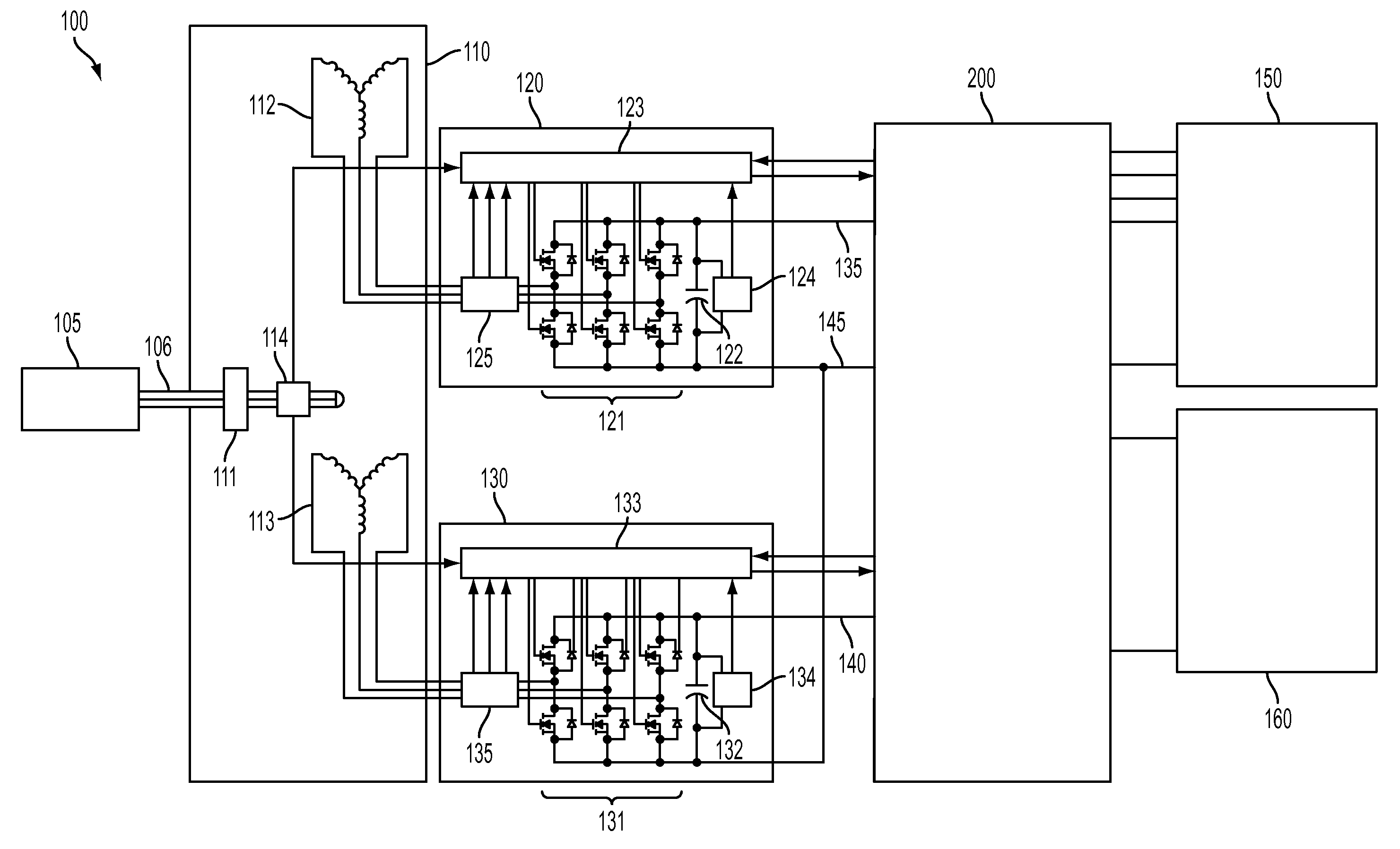
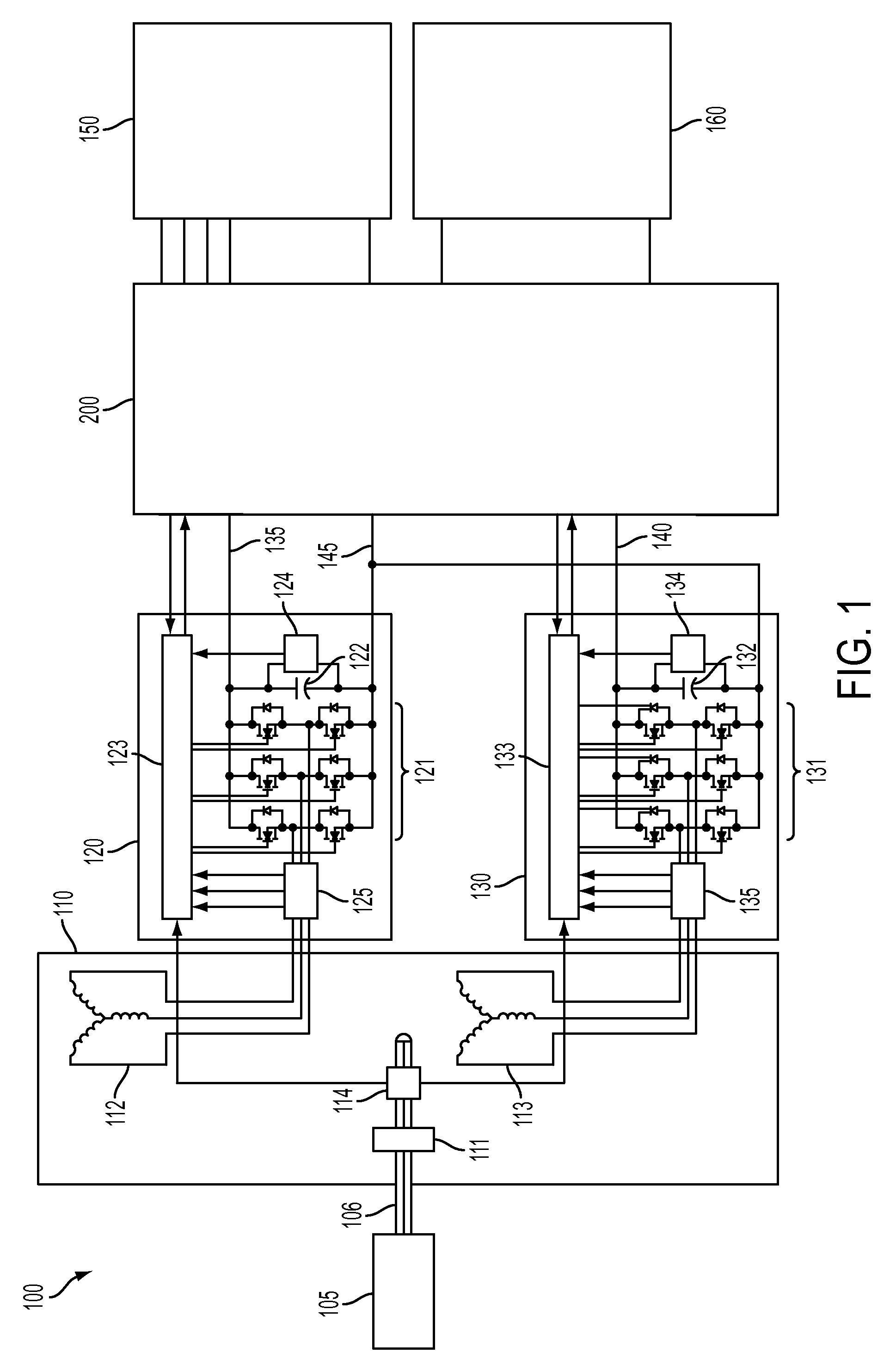
[0013]FIG. 1 illustrates a schematic diagram of an exemplary DC power generation, management and distribution system 100. In one embodiment, the system 100 includes a prime mover 105, which can be any engine that converts an energy source (e.g., fuel) to work, and more specifically an internal combustion engine or a gas turbine engine. The system 100 further includes a permanent magnet synchronous machine (machine) 110 coupled to the prime mover 105 via a shaft 106. The shaft 106 is coupled to a permanent magnet 111 that is disposed in the machine 110. The machine 110 further includes first armature winding 112 and a second armature winding 113. It will be appreciated that the prime mover 105 may be selectively energized, which rotates the shaft 106, causing the permanent magnet 111 to induce a current (e.g., an alternating current (AC)) in the first and second armature windings 112, 113. The system 100 further includes first and second active rectifiers 120, 130 respectively couple...


PUM


Abstract

A direct current generating, management and distribution system includes a first armature winding, a first active rectifier having a first controller and coupled to the first armature winding, a first direct current bus coupled to the first active rectifier, a second armature winding, a second active rectifier having a second controller and coupled to the second armature winding, a second direct current bus coupled to the second active rectifier, a unit controller coupled to the first and second controllers, a first set of switches coupled to the first direct current bus and to the unit controller, a second set of switches coupled to the second direct current bus and to the unit controller, a third switch coupled to the first direct current bus and to the unit controller and a fourth switch coupled to the second direct current bus and the unit controller.

Description

BACKGROUND OF THE INVENTION[0001]The present invention relates to direct current (DC) power systems, and more specifically, to a system that implements silicon carbide (SiC) metal on oxide field effect transistors (MOSFET) and silicon controlled rectifiers (SCR) for DC generation, power management, and DC power distribution.[0002]Power generating systems such as those that can be implemented in military ground vehicles employ a permanent magnet generator (PMG) coupled with an active rectifier, followed by the power management and distribution (PMAD) unit. Conventional PMAD units utilize electromechanical contactors for high current circuits. These conventional electromechanical power switches have very low voltage drop and losses, but suffer from several limitations that are addressed with solid state power controllers (SSPCs). Electromechanical switches have a very slow response time requiring many tens of milliseconds to switch. This speed limitation results in excessive let-throu...

Claims


Application Information

Patent Timeline
Patent Type & Authority Patents(United States)
IPC IPC(8): H02M7/48
CPCH02J1/00H02J5/00H02J2001/008Y10T307/505H02J1/082
Inventor ROZMAN, GREGORY I.GIERAS, JACEK F.MOSS, STEVEN J.
Owner HAMILTON SUNDSTRAND CORP
Why Eureka
Try Eureka