Optical system and optical equipment including the same
a technology of optical equipment and optical system, applied in the field of optical system, can solve the problems of large amount of unnecessary reflected light generated, flare and ghosting, and deterioration of image quality, and achieve the effect of small ghosting occurrence, excellent anti-reflection effect, and easy acquisition
- Summary
- Abstract
- Description
- Claims
- Application Information
AI Technical Summary
Benefits of technology
Problems solved by technology
Method used
Image
Examples
first embodiment
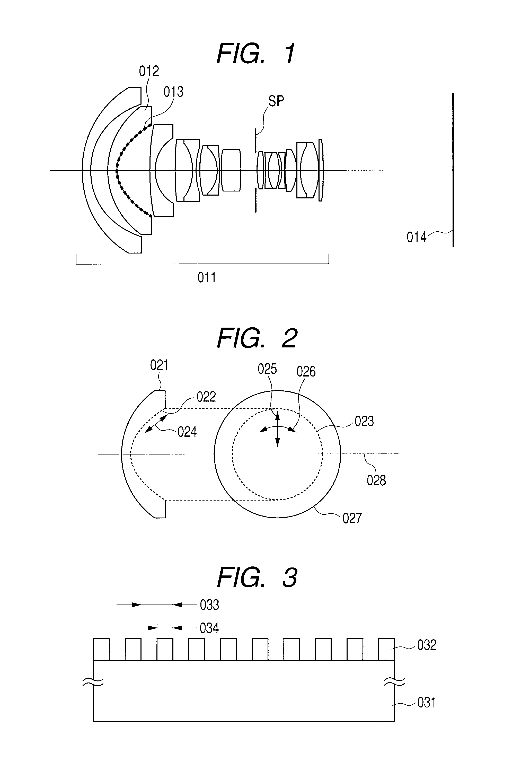
[0031]FIG. 1 is a cross-sectional view of lenses of an optical system according to a first embodiment of the present invention. When the optical system of the first embodiment is used as an image pickup optical system, a left hand in the figure is an object side, and a right hand is an image side. On the other hand, the optical system may be used for a projection optical system such as a projector. In this case, the left hand is a screen, and the right hand is an image to be projected. In this embodiment, an example in which the optical system is used as the image pickup optical system is described below.
[0032]Referring to FIG. 1, an image pickup optical system 011 is of a retrofocus type. An aspherical lens 012 includes a lens surface of an aspherical shape. The aspherical lens 012 includes an aspherical surface 013. An imaging plane is represented by 014. An aperture stop is represented by SP. Table 1 shows a detailed numerical embodiment of the image pickup optical system accordi...
second embodiment
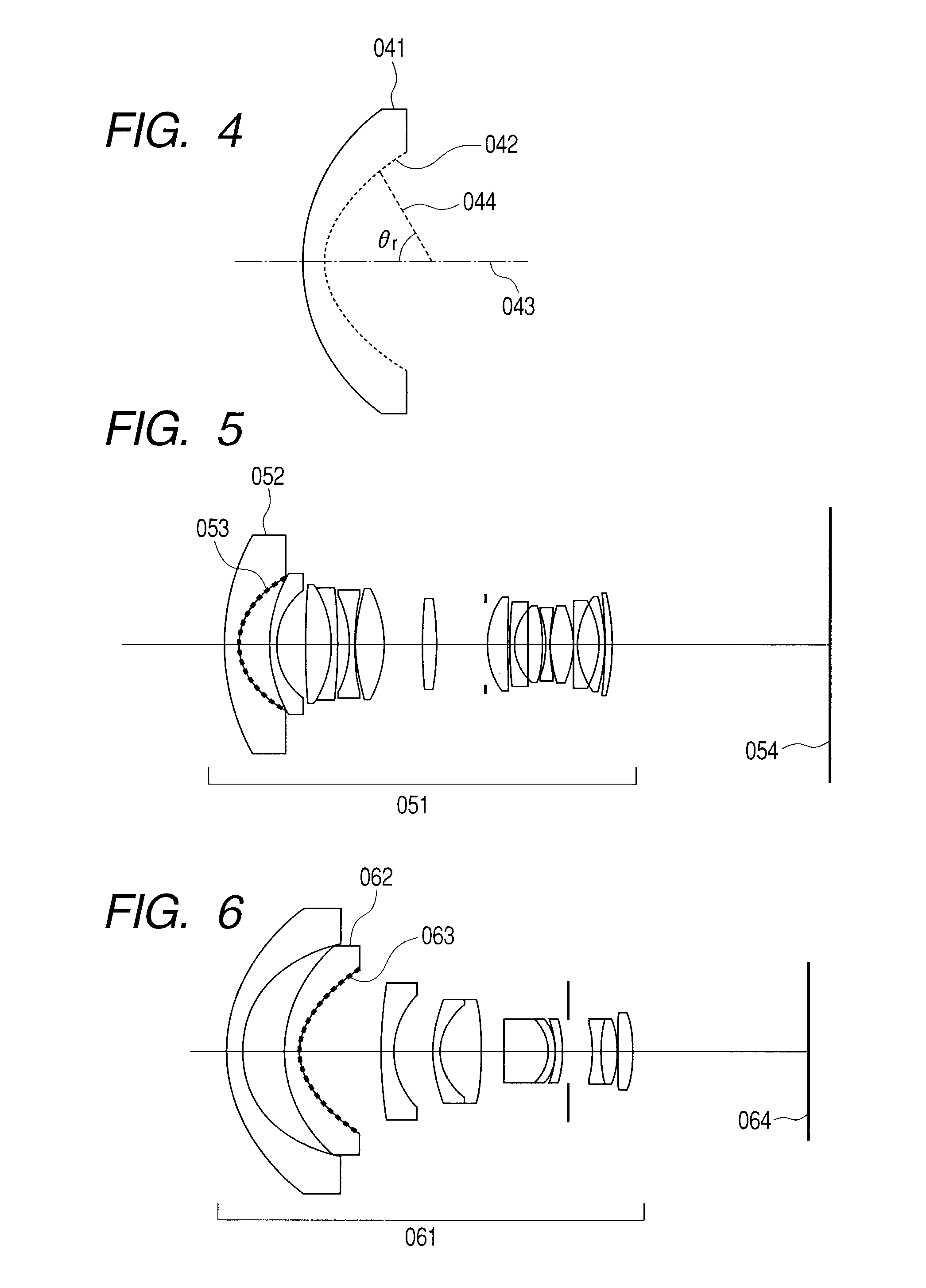
[0058]FIG. 5 is a cross-sectional view of lenses in an optical system according to a second embodiment of the present invention. In the figure, an image pickup optical system is represented by 051, an aspherical lens is represented by 052, an aspherical surface is represented by 053, and an imaging plane is represented by 054. In this embodiment, an image side surface of a first lens from the object side is the aspherical surface 053. The aspherical surface 053 is provided with an anti-reflection structure formed of structural parts made of an inorganic material and finer than the used wavelength. A second numerical embodiment of the second embodiment is shown in Table 2 like the first numerical embodiment.
[0059]In this embodiment, the aspherical surface 053 is 7.9×10⁻⁴ in the value on the left-hand side of Expression (2), which satisfies the condition of Expression (2). For that reason, ghost occurring on the aspherical surface 053 is liable to be a heteromorphous image. Under the ...
third embodiment
[0061]FIG. 6 is a cross-sectional view of lenses in an optical system according to a third embodiment of the present invention. In the figure, an image pickup optical system is represented by 061, an aspherical lens is represented by 062, an aspherical surface is represented by 063, and an imaging plane is represented by 064. In this embodiment, an image side surface of a second lens from the object side is the aspherical surface 063. The aspherical surface 063 is provided with an anti-reflection structure formed of structural parts made of an inorganic material and finer than the used wavelength. A third numerical embodiment of the third embodiment is shown in Table 3 like the first numerical embodiment. The aspherical surface 063 is 8.4×10⁻¹ in the value on the left-hand side of Expression (2), which satisfies the condition of Expression (2). For that reason, ghost occurring on the aspherical surface 063 is liable to be a heteromorphous image. Under the circumstance, when the anti...
PUM
| Property | Measurement | Unit |
|---|---|---|
| half aperture angle | aaaaa | aaaaa |
| maximum half aperture angle | aaaaa | aaaaa |
| wavelength | aaaaa | aaaaa |
Abstract
Description
Claims
Application Information
 - R&D
- Intellectual Property
- Life Sciences
- Materials
- Tech Scout
- Unparalleled Data Quality
- Higher Quality Content
- 60% Fewer Hallucinations
Browse by: Latest US Patents, China's latest patents, Technical Efficacy Thesaurus, Application Domain, Technology Topic, Popular Technical Reports.
© 2025 PatSnap. All rights reserved.Legal|Privacy policy|Modern Slavery Act Transparency Statement|Sitemap|About US| Contact US: help@patsnap.com


