
Aberration-corrected and energy-filtered low energy electron microscope with monochromatic dual beam illumination

a dual-beam illumination, electron microscope technology, applied in the direction of magnetic discharge control, instruments, therapy, etc., can solve the problems of unavoidable damage to many types of specimens, lack of energy-filtered imaging, and lateral resolution of conventional leem/peem

Active Publication Date: 2014-05-20
ELECTRON OPTICA
View PDF16 Cites 19 Cited by
  • Summary
  • Abstract
  • Description
  • Claims
  • Application Information

AI Technical Summary

Benefits of technology

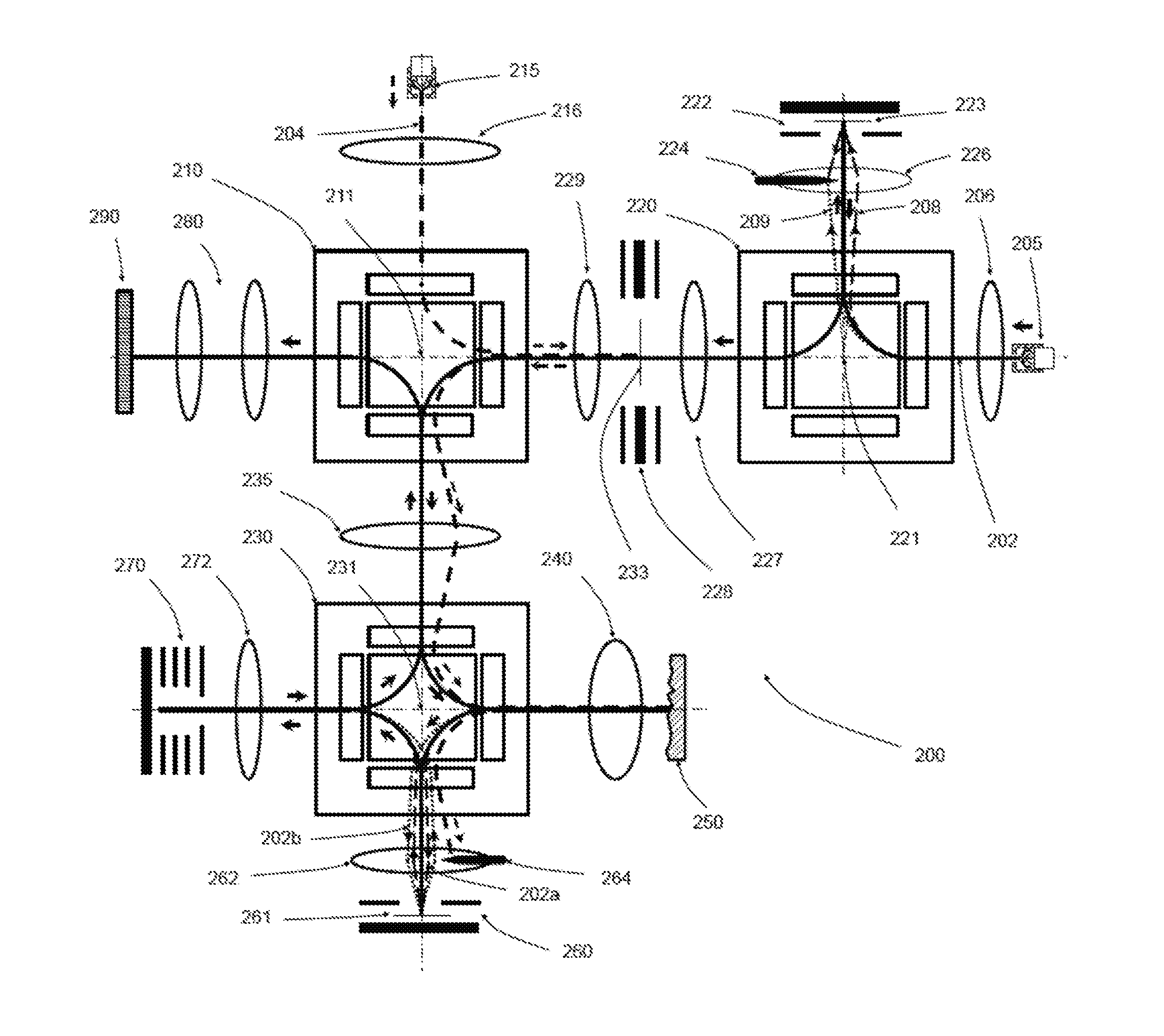
The patent describes an apparatus and method for generating an aberration-corrected, energy-filtered image of a specimen illuminated with electron beams. The apparatus includes a first electron beam source, a monochromator, and a knife-edge plate to remove high-energy electrons. The low-energy electron beam is then deflected and introduced into a second electron mirror, which corrects for aberrations. The energy-dispersed electron beam is then focused onto a projection optics and magnified on a viewing screen. The method involves using a cathode objective lens to image the specimen with both electron and UV or X-ray photon beams, and deflecting the electron beam with energy dispersion towards a first electron mirror before correction. The apparatus and method provide improved image quality and accuracy when using electron beams for specimen imaging.

Problems solved by technology

The low landing energy of electrons is also critical for avoiding radiation damage, as high energy electrons in all keV kinetic energy ranges can cause unavoidable damage to many types of specimens.
One of the main drawbacks of conventional LEEM / PEEM is lateral resolution.
Another drawback of a conventional LEEM / PEEM is its lack of energy-filtered imaging.
However, this prior technique is disadvantageous in some aspects.
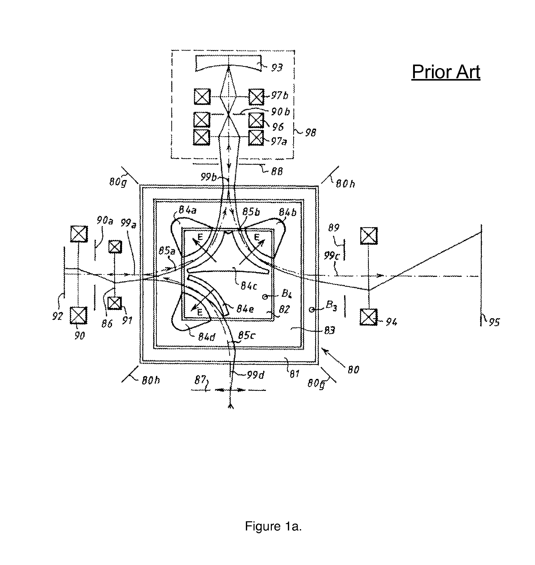
The practical implementation of this approach is rather difficult, due to complexity of the magnetic beam separator.
The dispersion-free beam separator is a rather complicated electron-optical element, consisting of a large number of coils with complex shapes that are difficult to construct and align.
The machining, tight tolerances and assembly are challenging which makes tuning and alignment of the whole microscope difficult.
In addition, the dispersion-free magnetic prism separator cannot be used for energy filtering, and an additional energy filter must be included in the projection optics which further complicates the microscope design, assembly and alignment.
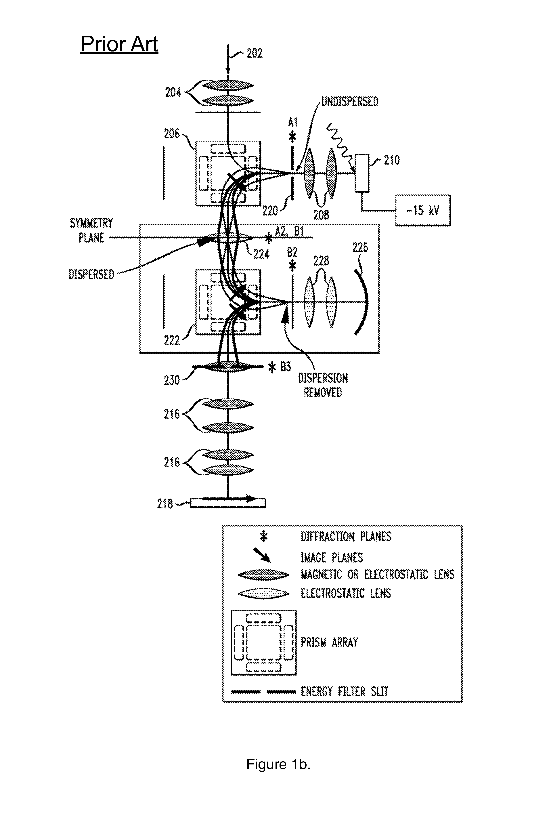
However, this technique using two beam separators is disadvantageous in some aspects.
The additional deflection that transports the beam into the projection optics introduces energy dispersion that generates additional combination aberrations, including image tilt and off-axis astigmatism which can affect the image quality when sub-nm resolution is needed.
In addition, the two beam separators have to be identical to ensure that the dispersion and all combination aberrations of the first prism separator are cancelled by the second prism separator, which may be difficult to achieve practically.
The prior technique disclosed by Tromp in U.S. Pat. No. 7,348,566 may result in additional combination aberrations in the projection optics including image tilt and off-axis astigmatism which can affect the final image quality.
In addition, small differences in the geometry and excitation between the two energy-dispersive magnetic beam separators may result in incomplete cancellation of the dispersion combination aberrations, which may prevent the aberration corrector from fully correcting the objective lens aberrations.
Another important drawback of a conventional LEEM / PEEM is its lack of imaging capability for insulating samples.
When a conventional LEEM instrument is used to image insulating specimens, the low landing energy exacerbates charging effects resulting in significantly reduced image quality.
The imbalance between the arriving and leaving flux of electrons causes the surface to charge up, resulting in increased blur and distortions.
In many cases, the built-up surface charge can rapidly discharge in an arc, resulting in specimen damage.
However, this approach restricts the landing energy and typically does not work when different insulating materials are present on the surface.
However, this prior technique is disadvantageous in some aspects.
The practical implementation of this approach is rather difficult, due to the small difference in deflection angles.
This means that the guns must be impractically far from the prism in order not to overlap.
However this is not desirable due to increased Coulomb interactions and geometric aberrations that deteriorate the spatial resolution.
In addition, it complicates the design and increases the likelihood of high-voltage arcing.
However, this prior technique using a dual-beam electron gun is disadvantageous in some aspects.
The proximity of the two cathodes in the gun at different temperatures and potentials results in complex crosstalk effects, beam current drift and long settling times, which makes it difficult for practical use and may reduce stability and reliability of the electron beam apparatus.
However, this prior technique is disadvantageous in some aspects.
However, none of the above-mentioned prior dual-beam beam approaches allow for aberration correction, monochromatic illumination and energy filtered imaging.
In addition, none of the above-mentioned aberration-correction and energy-filtering approaches allow for dual beam illumination.

Method used


Image

  • Aberration-corrected and energy-filtered low energy electron microscope with monochromatic dual beam illumination
  • Aberration-corrected and energy-filtered low energy electron microscope with monochromatic dual beam illumination
  • Aberration-corrected and energy-filtered low energy electron microscope with monochromatic dual beam illumination

Examples


Embodiment Construction

An Aberration-Corrected, Energy-Filtered, Dual Beam LEEM / PEEM

[0042]While some of the above discussed prior apparatus and methods provide aberration correction and energy filtering, they do not allow for dual beam illumination. Other discussed prior apparatus and methods provide for dual beam illumination, however they do not allow for aberration correction, monochromatic illumination and energy filtered imaging. Improved apparatus and methods for providing aberration correction, energy filtering and dual beam illumination in a single LEEM / PEEM instrument are desirable. One distinct technique for providing aberration-corrected imaging, energy filtering and dual electron beam illumination with a monochromator in a single apparatus is disclosed herein and discussed below.

[0043]Unlike the prior technique of Rose et al. (FIG. 1a) employing a dispersion-free magnetic beam separator and an electron mirror for aberration correction, the presently disclosed apparatus and method does not requ...


PUM

PropertyMeasurementUnit
diameteraaaaaaaaaa
landing energyaaaaaaaaaa
deflection anglesaaaaaaaaaa

Abstract

One embodiment relates to an apparatus for correcting aberrations introduced when an electron lens forms an image of a specimen and simultaneously forming an electron image using electrons with a narrow range of electron energies from an electron beam with a wide range of energies. A first electron beam source is configured to generate a lower energy electron beam, and a second electron beam source is configured to generate a higher energy electron beam. The higher energy beam is passed through a monochromator comprising an energy-dispersive beam separator, an electron mirror and a knife-edge plate that removes both the high and low energy tail from the propagating beam. Both the lower and higher energy electron beams are deflected by an energy-dispersive beam separator towards the specimen and form overlapping illuminating electron beams. An objective lens accelerates the electrons emitted or scattered by the sample. The electron beam leaving the specimen is deflected towards a first electron mirror by an energy-dispersive beam separator, which introduces an angular dispersion that disperses the electron beam according to its energy. A knife-edge plate, located between the beam separator and first electron mirror, is inserted that removes all of the beam with energy larger and smaller than a selected energy and filters the beam according to energy. One or more electron lenses focus the electron beam at the reflection surface of the first electron mirror so that after the reflection and another deflection by the same energy-dispersive beam separator the electron beam dispersion is removed. The dispersion-free and energy-filtered electron beam is then reflected in a second electron mirror which corrects one or more aberrations of the objective lens. After the second reflection, electrons are deflected by the magnetic beam separator towards the projection optics which forms a magnified, aberration-corrected, energy-filtered image on a viewing screen.

Description

FEDERAL SUPPORT[0001]This invention was made with Government support under Grant Number R43HG006303 from the National Human Genome Research Institute (NHGRI) awarded by the PHS. The Government has certain rights in the invention.BACKGROUND OF THE INVENTION[0002]1. Field of the Invention[0003]The present invention relates generally to electron beam apparatus and electron microscopy methods.[0004]2. Description of the Background Art[0005]Optical microscopes, the simplest and most common instruments used to image objects too small for the naked eye to see, uses photons with visible wavelengths for imaging. A specimen is illuminated with a broad light beam, and a magnified image of the specimen can be observed using an eyepiece or camera. The maximum magnification of a light microscope can be more than 1000× with a diffraction-limited resolution limit of a few hundred nanometers. Improved spatial resolution in an optical microscope can be achieved when shorter wavelengths of light, such...

Claims


Application Information

Patent Timeline
Patent Type & Authority Patents(United States)
IPC IPC(8): H01J37/153H01J37/05H01J37/29G01N23/225
CPCH01J2237/05H01J37/261H01J2237/2538H01J2237/0492H01J2237/0044H01J37/04H01J37/285H01J2237/0042H01J37/29H01J37/026H01J2237/1534
Inventor MANKOS, MARIAN
Owner ELECTRON OPTICA
Learn More