Control system for starting electrically powered implements
a control system and electrical power technology, applied in the direction of electric control, multiple dynamo-motor starters, instruments, etc., can solve the problems of reducing precipitously, not staying at the maximum available electrical power output of alternators, etc., and reducing the dynamic effect of large load changes
- Summary
- Abstract
- Description
- Claims
- Application Information
AI Technical Summary
Benefits of technology
Problems solved by technology
Method used
Image
Examples
first embodiment
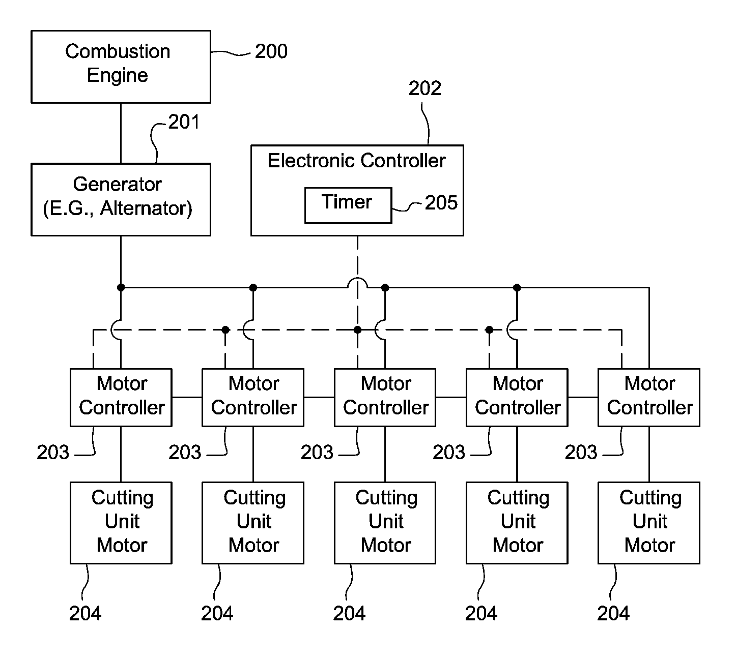
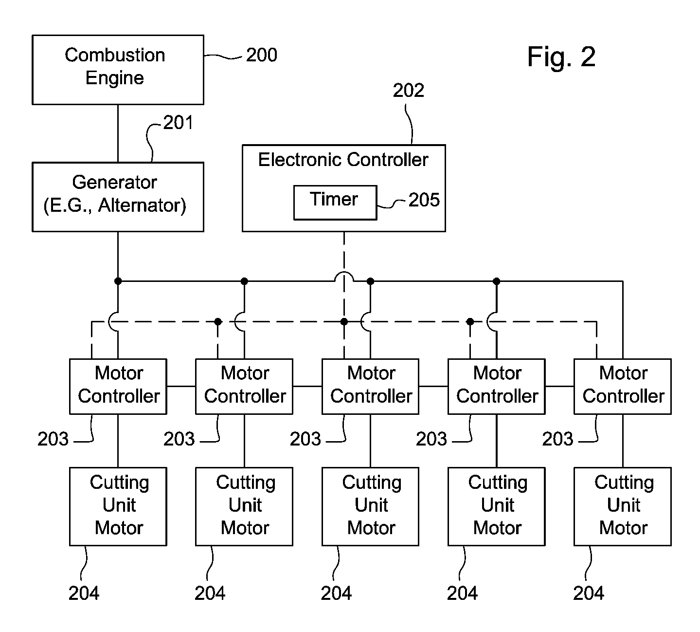
[0020]As shown in FIG. 3, in a logic diagram for the control system for starting electrically powered implements, an operator may turn the cutting units on in block 301. In block 302, the electronic controller begins the start sequence by sending a signal to the first motor controller to start the first cutting unit motor. Alternatively, in block 302 the electronic controller may begin the start sequence by sending a signal to a selected group of motor controllers to start several cutting unit motors. In block 303, a pre-defined time constant (t) may be stored in the electronic controller. In block 304, when the start sequence begins, the electronic controller starts a timer. In block 305, the controller checks if the timer value is greater than or equal to time constant (t). If the controller determines that the timer value is less than time constant (t), the controller reads the timer value again at periodic intervals or clock cycles. If the controller determines that the timer va...
second embodiment
[0021]In FIG. 4, in a logic diagram for the control system for starting electrically powered implements, an operator turns the cutting units on in block 401. In block 402, the electronic controller begins the start sequence by sending a signal to a first motor controller to start the first cutting unit motor. Alternatively, in block 402 the electronic controller may begin the start sequence by sending a signal to a selected group of motor controllers to start several cutting unit motors. In block 403, a Voltage constant (v) is stored in the electronic controller. In block 404, a voltage input signal is reported from the motor controller that was just started. Alternatively, voltage input signals may be reported from any one of the motors being started. In block 405, the electronic controller reads the voltage input from the motor controller. In block 406, the electronic controller determines if the voltage input from the motor controller is greater than or equal to the Voltage const...
fourth embodiment
[0023]FIG. 6 is a logic diagram showing the control system for starting electrically powered implements. An operator turns the cutting units on in block 601. In block 602, the electronic controller begins the start sequence by sending a signal to a first motor controller to start the first cutting unit motor. Alternatively, in block 602 the electronic controller may begin the start sequence by sending a signal to a selected group of motor controllers to start several cutting unit motors. In block 603, a Speed constant (ω) is stored in the electronic controller. In block 604, a speed input signal is reported from the last motor controller that was started. In block 605, the electronic controller reads the speed input from the motor controller. In block 606, the electronic controller determines if the speed input from the motor controller is greater than or equal to Speed constant (ω). If the controller determines that the speed input is less than Speed constant (ω), the controller re...
PUM
 Abstract
Description
Claims
Application Information
 - R&D
- Intellectual Property
- Life Sciences
- Materials
- Tech Scout
- Unparalleled Data Quality
- Higher Quality Content
- 60% Fewer Hallucinations
Browse by: Latest US Patents, China's latest patents, Technical Efficacy Thesaurus, Application Domain, Technology Topic, Popular Technical Reports.
© 2025 PatSnap. All rights reserved.Legal|Privacy policy|Modern Slavery Act Transparency Statement|Sitemap|About US| Contact US: help@patsnap.com


